background image

10

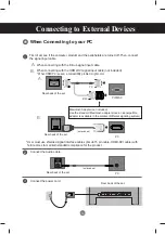
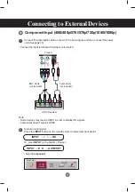
First of all, see if the computer, product and the peripherals are turned off. Then, connect 

the signal input cable.

When connecting with the D-Sub signal input cable.
When connecting with the HDMI-DVI signal input cable (not included).

* When HDMI PC is used, a compatiblity problem might occur.

MAC

Macintosh Adapter (not included)
Use the standard Macintosh adapter since an incompatible 
adapter is available in the market. (Different signaling system)

Rear back of the set.

Connecting to External Devices

Connect the power cord.

PC

PC/MAC

PC

Rear back of the set.

Rear back of the set.

PC

Rear back of the set.

Connect the Audio cable.

 (not included)

 (not included)

*  User must use shielded signal interface cables (D-sub 15 pin cable, HDMI-DVI cable) with 

ferrite cores to maintain standard compliance for the product. 

When Connecting to your PC

1

2

3

B.

B.

A.

A.

Summary of Contents for M4214C

Page 1: ...www lg com OWNER S MANUAL MONITOR SIGNAGE MONITOR SIGNAGE MODELS M4214C Please read this manual carefully before operating your set and retain it for future reference ENGLISH ...

Page 2: ...agement 15 Video Input 16 Component Input 480i 480p 576i 576p 720p 1080i 1080p 17 HDMI Input 480p 576p 720p 1080i 1080p 18 User Menus 19 Screen Adjustment options 19 OSD Menu 21 How to adjust the OSD On Screen Display screen 22 How to adjust the screen automatically 22 Adjusting Screen Color 23 Adjusting the audio function 29 Adjusting the timer function 30 Selecting the options 31 Adjusts the til...

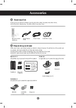
Page 3: ...wn here Thank you for your purchase Please check the product as well as the accessories shown below Note that the accessories may look different from those shown here Speaker kit Applicable only for models that support the speakers Stand kit Applicable only for models that support the stand Remote Control Batteries CD ROM Cards D Sub Signal Cable Speaker 2 NC2000 CD ROM Cards Screws 2 Screws 4 Cab...

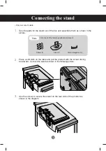
Page 4: ... picture Place a soft cloth on the table and put the product with the screen facing downward Connect the stand as shown in the following picture Use the screws to secure the stand on the rear side of the product as shown in the diagram First check if the following parts are all present Parts Stand 1 Screws 6 Cable management 1 ...

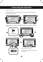
Page 5: ... cable When the speaker is installed Connect the input terminal with a proper color match Remove the paper Cable holder After installing your speakers use holders and cable ties to organize the speaker cables This feature is not available in all model Cable tie This feature is not available in all model Only on some models ...

Page 6: ...6 To install Portrait When installing Portrait rotate it clockwise based on its front Only on some models ...

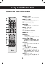
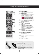
Page 7: ...rSign input only Volume Up Down Button Adjusts the volume PSM Button Selects the Picture Status Mode MUTE Button Switches the sound on or off MENU Button Selects a menu Clears all on screen displays and returns to TV viewing from any menu Up Down Left Right Buttons Allows you to navigate the on screen menus and adjust the system settings to your preferenc OK Button Accepts your selection or displa...

Page 8: ...ttons on the remote control In USB mode the OSD menu has the Page function to move to the next file list AUTO Button Automatically adjusts picture position and minimizes image instability RGB input only S MENU Button SuperSign Menu Key Selects the SuperSign OSD Menu SuperSign input only EXIT Button Clears all on screen displays and returns to monitor viewing from any menu TILE button Selects the T...

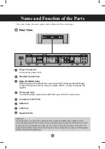
Page 9: ... Line Out convert to Line Out using the card jumper of the program Refer to the Sound Card Manual The product image in the user s guide could be different from the actual image Power Connector Connect the power cord RS 232C Serial Ports RGB HDMI DVI Ports HDMI Supports High Definition input and HDCP High bandwidth Digital Content Protection Some devices require HDCP in order to display HD signals ...

Page 10: ...luded Use the standard Macintosh adapter since an incompatible adapter is available in the market Different signaling system Rear back of the set Connecting to External Devices Connect the power cord PC PC MAC PC Rear back of the set Rear back of the set PC Rear back of the set Connect the Audio cable not included not included User must use shielded signal interface cables D sub 15 pin cable HDMI ...

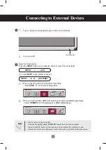
Page 11: ...unded power outlet on the wall or a power bar with a ground wire Note Turn on power by pressing the power button on the product Turn on the PC When connecting with a D Sub signal input cable Select RGB 15 pin D Sub analog signal When connecting with a HDMI DVI signal input cable and HDMI Signal Cable Select HDMI DVI DVI Digital signal or HDMI Digital signal Connecting to External Devices INPUT OK ...

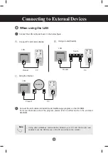
Page 12: ...AN cable as shown in the below figure Connect the LAN cable and install the eZ Net Manager program on the CD ROM For more information about the program please refer to eZ Net Guide in the enclosed CD ROM Connect PC to Monitor directly Using a router Switch PC Product Network Network Product LAN PC LAN Switch Using the Internet PC Product Network LAN When using the LAN 1 2 B A C Note ...

Page 13: ...nnector of other products Product 1 Product 2 Product 3 Product 4 15 pin D Sub Signal Cable PC Video PC BNC Cable not included Audio Cable not included Product 1 Product 2 Product 3 The number of monitors that can be connected to one output may vary depending on signal status and cable loss If the signal status is good and there is no cable loss it is possible to connect up to 9 monitors If you wa...

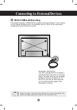
Page 14: ...t home page of the Kensington company This product supports a VESA FDMI compliant mounting interface These mounts are purchased separately and not available from LG Refer to the instructions included with wall mount for more info Connecting to External Devices VESA FDMI wall Mounting There is a switch on the lower side of the back You can set the switch to On before connecting a power cord to make...

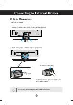
Page 15: ...ent Hold the Cable management with both hands and pull it downward Removing the cable guide Do not use the cable management as a handle for the Monitor Arrange the cables in the center as shown in the following picture Fit the cable guide to the back to help manage the cables 2 1 Note ...

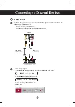
Page 16: ...en connecting with a BNC cable Connect the input terminal with a proper color match BNC Cable not included Product VCR DVD Receiver Select an input signal Press the INPUT button on the remote control to select the input signal Or press INPUT on the bottom of the set Audio Cable not included Video Input INPUT OK 1 2 INPUT AUTO SET Input List AV Component RGB HDMI DVI SuperSign ...

Page 17: ...ver Select an input signal Press the INPUT button on the remote control to select the input signal Or press INPUT on the bottom of the set Audio Cable not included Connecting to External Devices Note Some devices may require HDCP in order to display HD signals Component doesn t support HDCP Component Input 480i 480p 576i 576p 720p 1080i 1080p INPUT OK 1 2 INPUT AUTO SET Input List AV Component RGB...

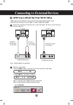
Page 18: ...t signal Or press INPUT on the bottom of the set HDMI Signal Cable not included Connecting to External Devices When connecting with a HDMI DVI signal input cable When connecting with a HDMI signal input cable Select HDMI DVI HDMI Supports High Definition input and HDCP High bandwidth Digital Content Protection Some devices require HDCP in order to display HD signals Note Dolby Digital is not suppo...

Page 19: ...rmally on mode If the display is in sleep Energy Saving mode this indicator color changes to amber On Off Button Adjust the volume Adjust the up and down Use this button to show hide the OSD On Screen Display menu screen MENU Button Use this button to select an icon or adjust the setting in the OSD screen OSD Select Adjust Button Power Indicator Volume 35 1 6 3 4 5 1 7 2 2 3 4 ...

Page 20: ... Video Component HDTV DVD RGB 15 pin D Sub analog signal HDMI DVI Digital signal SuperSign SuperSign Toggles between inputs INPUT Button IR Receiver When XGA Mode is active and 1920 x 1080 is selected Auto in progress For optimal display change resolution to 1920 x 1080 Auto in progress 5 7 6 INPUT AUTO SET Input List AV Component RGB HDMI DVI SuperSign ...

Page 21: ...es graphical presentation User Menus Icon Function Description Adjusts the audio options Adjusts screen brightness contrast and color that you prefer Adjusts the screen status according to the circumstances Adjusts the timer options Adjusts the tile options Adjusts the USB options Picture Audio Option Time Tile USB Note ...

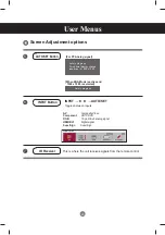
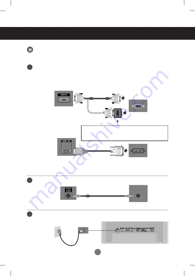
Page 22: ...adjust Move where you want to adjust Select a menu list Select a menu icon Adjust the status Save adjustment Exit from the menu screen When XGA Mode is active and 1920 x 1080 is selected Auto in progress MENU Press the MENU Button then the main menu of the OSD appears To access a control use the Buttons To access a control use the Buttons When the icon you want becomes highlighted press the OK But...

Page 23: ...des Zoom 4 3 programs are magnified until they fill the 16 9 screen The top and bottom will be cut off Cinena Zoom 1 Choose Cinema Zoom when you wish the picture to be altered both horizontally extended and vertically cropped The picture adopting a compromise between alteration and screen coverage Full Wide When TV receives the wide screen signal it will lead you to adjust the picture horizontally...

Page 24: ...vels are provided Off 100 light Level 1 80 light Level 2 60 light Level 3 40 light Move OK PICTURE Aspect Ratio 16 9 ꕫ Energy Saving Off Picture Mode Standard Backlight 70 Contrast 90 Brightness 50 Sharpness 70 Color 60 Energy Saving Off Off Level 1 Level 2 Level 3 Off If the Picture Mode is set to Cinema the Energy saving mode is disabled Note ...

Page 25: ... with a soft image Game To enjoy dynamic image when playing a game Expert1 2 Select this option to use the user defined settings If the Picture Mode setting in the Picture menu is set to Vivid Standard Cinema Sport or Game the subsequent menus will be automatically set Move OK PICTURE Aspect Ratio 16 9 Energy Saving Off Picture Mode Standard Backlight 70 Contrast 90 Brightness 50 Sharpness 70 Colo...

Page 26: ... of LCD panel Contrast Adjust the difference between the light and dark levels in the picture Brightness To adjust the brightness of the screen Sharpness To adjust the clearness of the screen This function can be used only under AV Component and HDMI DVI DTV Color To adjust the color to desired level This function can be used only under AV Component and HDMI DVI DTV Tint To adjust the tint to desi...

Page 27: ...V Gamma Set your own gamma value On the monitor high gamma values display whitish images and low gamma values display high contrast images Black Level Function works in the following mode AV Component HDMI DTV adjusts the contrast and the brightness of the screen using the black level of the screen Low The reflection of the screen gets darker High The reflection of the screen gets brighter Film Mo...

Page 28: ...oving the screen position Size Adjust the size of the screen Phase To adjust the focus of the display This item allows you to remove any horizontal noise and clear or sharpen the image of characters This function is available for analog signals only Reset Return Manual config to the default factory settings Move OK PICTURE Contrast 90 Brightness 50 Sharpness 70 Color 60 Tint 0 Advanced Control Pic...

Page 29: ...at you re currently watching Standard The most commanding and natural audio Music Select this option to enjoy the original sound when listening to the music Cinema Select this option to enjoy sublime sound Sport Select this option to watch sports broadcasting Game To enjoy dynamic sound when playing a game Speaker You can adjust internal speaker status If you want to use your external hi fi stereo...

Page 30: ...ime automatically switches the set to standby at the pre set time 1 Press the MENU button and then use button to select the Time menu input OK button to enter 2 Press the button and then use button to select On Off Timer 3 Press the button and then use button to select date 4 Press the button and then use button to set the hour 00h to 23h 5 Press the button and then use button to set the minutes 0...

Page 31: ... connected for display Specify the number 1 to 99 using the button and exit Use the assigned Set ID to individually control each product using the Product Control Program ISM Method Leaving a fixed image on the screen for a long time may cause damage to the screen and cause image burn in To use the product for a long period of time use a screen saver on the PC or utilize the residual image prevent...

Page 32: ...mpleted is displayed at the bottom of the screen While Wait for IP Setup is displayed you cannot use the local keys and remote control Wait for IP Setup is displayed for up to 40 seconds If Interface select is set to RS232C DHCP and Manual are disabled Information You can find informations about Serial No F W version IP Address and MAC Address Factory Reset Select this option to return to the defa...

Page 33: ... RGB Out It is used to enlarge the screen and also used with several products to view screen Tile Mode Tile mode column x row c 1 2 3 4 5 r 1 2 3 4 5 5 x 5 available Configuration of an integration screen is also available as well as configuration of One by one Display Tile mode product 1 4 c 2 x r 2 Adjusts the tile options User Menus ID1 ID ID ID4 column row 3 2 Move TILE OK Tile Mode Off Tile I...

Page 34: ... Natural The image is omitted by the distance between the screens to be naturally shown H Size Adjust the horizontal size of the screen taking into account the size of the bezel V Size Adjust the vertical size of the screen taking into account the size of the bezel H Position Moving the screen position horizontally V Position Moving the screen position vertically Reset Function to initialize and r...

Page 35: ...while the OSD including Menu EPG or Schedule list is activated When the Pop Up menu appears you can select Music List Photo List or Movie List in the MY MEDIA menu In USB device you can not add a new folder or delete the existing folder Select PHOTO LIST MUSIC LIST or MOVIE LIST Connect the USB device to the USB jack on the product PHOTOLIST MUSICLIST MOVIELIST 2 1 USB 메모리 스틱 ...

Page 36: ... in the NTFS file system Please connect power to a USB storage device which requires an external power supply If not the device may not be recognized Please connect a USB storage device with cable is offered by USB maker If connected with cable is not offered by USB maker or an excessively long cable the device may not be recognized Some USB storage devices may not be supported or operated smoothl...

Page 37: ... Photo List Page 2 3 Drive1 JMJ001 1366x768 125KB Up Folder Up Folder KY101 02 12 2010 KY102 02 12 2010 JMJ001 02 12 2010 JMJ002 02 12 2010 JMJ003 02 12 2010 JMJ004 02 12 2010 KY103 02 12 2010 KY104 02 12 2010 KY105 02 12 2010 JMJ005 02 12 2010 JMJ006 02 12 2010 JMJ007 02 12 2010 JMJ008 02 12 2010 No Marked Option Mark Navigation Page Change Exit MARK EXIT USB Device Free Space 150 MB Screen Compo...

Page 38: ...tion and PopUp Menu Photo List Page 2 3 Drive1 JMJ001 1366x768 125KB Up Folder Up Folder KY101 02 12 2010 KY102 02 12 2010 JMJ001 02 12 2010 JMJ002 02 12 2010 JMJ003 02 12 2010 JMJ004 02 12 2010 KY103 02 12 2010 KY104 02 12 2010 KY105 02 12 2010 JMJ005 02 12 2010 JMJ006 02 12 2010 JMJ007 02 12 2010 JMJ008 02 12 2010 No Marked USB Device Free Space 150 MB Option Mark Navigation Page Change Exit MAR...

Page 39: ...unction ꘤ Rotate Rotate photos Rotates the photo 90 180 270 360 clockwise Delete Delete photos Option Set values for Sl ide Speed and Music Folder for BGM Use button and OK button to set values Press OK to save the settings You cannot change Music Folder while BGM is playing Hide Hide the menu on the full sized screen To see the menu again on the full sized screen press OK button to display How to...

Page 40: ... MUSIC MP3 supporting file Bit rate 32 to 320kbps Sampling rate MPEG1 layer 3 32 kHz 44 1 kHz 48 kHz Adjusts the USB options Music List Music List Page 2 3 Music S003 00 00 01 34 Up Folder Title Duration Up Folder S001 S002 S003 S004 S005 Up Folder 03 33 04 45 01 30 02 37 01 58 No Marked USB Device Free Space 150 MB Screen Components 1 5 2 3 4 Moves to upper level folder Current page Total pages T...

Page 41: ...tion Mark Navigation Page Change Exit MARK EXIT Play During stop Play the selected music titles One playback of a piece of music finishes the next selected one will be played When there are no selected music titles to play the next one in the current folder will be played If you go to a different folder and press the OK button the current music in playback will stop Play Marked Play the selected m...

Page 42: ...ded period of time A damaged or corrupted music does not play but displays 00 00 in playtime A music downloaded from a paid service with copyright protection does not start but displays inappropriate information in playtime If you press OK buttons screen saver is stopped The PLAY Pause II buttons on the remote control are also avail able in this mode You can use the button to select the next music...

Page 43: ...ypes or recording methods If the video and audio structure of recorded file is not interleaved either video or audio is outputted Maximum FPS Frame Per Second can be reached only at SD level FPS is 25 FPS 720 576 or 30 FPS 720 480 depending on Resolution Max bitrate of playable DivX is 4Mbps Files more than 25 FPS or 30 FPS or higher may not be played properly A DivX movie file and its subtitle fi...

Page 44: ...st Screen Components 1 5 2 3 4 Moves to upper level folder Current page Total pages Total number of marked movie title Usable USB memory Corresponding buttons on the remote control 1 2 4 3 5 Use the left right keys to move to a specific frame forward or backward while playing a movie The left right keys may not work properly for some files while playing a movie Option Mark Navigation Page Change E...

Page 45: ...ge regarding non supported file is displayed Option Mark Navigation Page Change Exit MARK EXIT Option Mark Navigation Page Change Exit MARK EXIT Play Play the selected movie DivX Play is executed while screen changes Mark All Mark all Movie in the folder Unmark All Deselect all marked movies Delete Delete the selected Movie item Close Close the pop up menu Using the remote control When playing rep...

Page 46: ...tracks This option is not available if the file has only one subtitle track Audio Language Allows to select the language you want for the file with multiple audio tracks This option is not available if the file has only one audio track Subtitle File Sets to On or Off Language Sets to one of Latin1 Latin2 Latin4 Latin5 Cyrillic Greek Hebrew Chinese Japanese and Korean Sync Adjusts the subtitle dela...

Page 47: ...files matched with the registration code of the purchased TV are playable DivX Registration Code DivX R Video On Demand Your registration Code is xxxxxxxxxx To learn more visit www divx com vod Close Close ABOUT DivX VIDEO DivX is a digital video format created by DivX Inc This is an official DivX Certified device that plays DivX video Visit www divx com for more information and software tools to ...

Page 48: ...tivate up to 6 devices under one account but to replace or deactivate any of those devices the consumer had to contact DivX Support and request deletion Now with this added feature consumers will be able to deactivate the device themselves and hence better manage their DivX VOD devices DivX R Video On Demand Do you want to deactivate your device Yes No DivX R Video On Demand This device is deactiv...

Page 49: ... See if the power cord is properly connected to the outlet See if the power switch is turned on May need service Adjust brightness and contrast again Backlight may need repair If the set is in power saving mode move the mouse or press any key Turn both devices off and then back on The signal from the PC video card is out of the vertical or horizontal frequency range of the set Adjust the frequency...

Page 50: ... Sub analog signal Press the AUTO button in the remote control to automatically select an optimal screen status that fits into the current mode If adjustment is not satisfactory use the Phase OSD menu The proper input signal is not connected to the signal port Connect the signal cable that matches with the source input signal If you use a fixed image for a long time the pixels may be damaged quick...

Page 51: ...6 colors Screen color is unstable or mono colored Do black spots appear on the screen See if the audio cable is connected properly Adjust the volume See if the sound is set properly Select the appropriate equalize sound Adjust the volume No sound Sound is too dull Sound is too low Is the sleep timer set Check the power control settings Power interrupted CAUTION FAN STOP If the power is turned off ...

Page 52: ...0 240 V 50 60 Hz 2 7 A Power Consumption On Mode 200 W Typ Sleep Mode 1 W RGB 2 W HDMI DVI If LAN OFF is selected Off Mode 0 5 W Width x Height x Depth 1 99 56 cm 39 2 inch x 58 76 cm 23 1 inch x 11 37 cm 4 5 inch 2 99 56 cm 39 2 inch x 67 41cm 26 5 inch x 29 30 cm 11 5 inch 3 99 56 cm 39 2 inch x 58 76 cm 23 1 inch x 11 37 cm 4 5 inch 4 99 56 cm 39 2 inch x 67 41cm 26 5 inch x 29 30 cm 11 5 inch ...

Page 53: ...rizontal Frequency RGB 30 kHz to 83 kHz HDMI DVI 30 kHz to 83 kHz Vertical Frequency RGB 56 Hz to 75 Hz HDMI DVI 56 Hz to 60 Hz Synchronization Type Composite Separate Digital 15 pin D Sub type HDMI DVI digital Composite Video Component RS 232C LAN USB Operational Condition Temperature 0 C to 40 C Humidity 10 to 80 Storage Condition Temperature 20 C to 60 C Humidity 5 to 95 Video Signal Input Conn...

Page 54: ...x 480 800 x 600 800 x 600 832 x 624 1024 x 768 1024 x 768 1280 x 720 31 469 31 468 31 469 37 5 37 879 46 875 49 725 48 363 60 123 44 772 70 8 70 8 59 94 75 60 317 75 74 55 60 75 029 59 855 11 12 13 14 15 16 17 1280 x 768 1360 x 768 1366 x 768 1280 x 1024 1280 x 1024 1680 x 1050 1920 x 1080 47 7 47 72 47 7 63 981 79 98 65 290 67 5 60 59 799 60 60 02 75 02 59 954 60 Mode Product On Mode Sleep Mode O...

Page 55: ... by connecting them to a single PC If the Set ID menu in Option is set to OFF the monitor ID value should be set between 1 and 99 RS 232C Cable not included monitor 1 PC monitor 2 monitor 3 monitor 4 7 Wire Configurations Standard RS 232C cable RXD TXD GND DTR DSR RTS CTS TXDRXD GND DSR DTR CTS RTS PC Monitor 2 3 5 4 6 7 8 3 2 5 6 4 8 7 D Sub 9 D Sub 9 Female Female 3 Wire Configurations Not Stand...

Page 56: ...01H f a 00H to 06H f d F1H to F4H E0H to E4H 01H to 80H f e F1H to F4H E0H to E4H 01H to 80H 01 Power 02 Input Select 03 Aspect Ratio 04 Screen Mute 05 Volume Mute 06 Volume Control 07 Contrast 08 Brightness 09 Color 10 Tint 11 Sharpness 12 OSD Select 13 Remote Lock key Lock 14 Balance 15 Color Temperature 16 Abnomal state 17 ISM mode 18 Auto configuration 19 Key 20 Tile Mode 21 Tile H Position 22...

Page 57: ...e 43 DPM Select 44 Reset 45 Power Saving 46 Power Indicator 47 Logo Indicator 48 Serial no 49 S W Version 50 Input Select f u F1H to F4H f f 00H to 08H f g 00H to 01H f h 00H to 64H f i 00H to 09H f j 00H to 01H f k 00H to 02H f l 00H to 03H f o 00H to 01H f p 00H to 01H f y FFH f z FFH x b 20H to A0H 02H to 09H The function may be disabled depending of the product ...

Page 58: ... Command 2 Second command a to u Set ID Set up the Set ID number of product range 01H to 63H by setting 0 server can control all products In case of operating with more than 2 sets using set ID as 0 at the same time it should not be checked the ack message Because all sets will send the ack message so it s impossible the check the whole ack messages DATA To transmit command data Transmit FF data t...

Page 59: ...ledgement Data 0 Power Off 1 Power On 02 Input Select Command b Main Picture Input To select input source for the Set You can also select an input source using the INPUT button on the remote control Transmission Data 2 AV 4 Component 7 RGB PC 8 HDMI DTV 9 HDMI PC Acknowledgement Data 2 AV 4 Component 7 RGB PC 8 HDMI DTV 9 HDMI PC k a Set ID Data Cr a Set ID OK Data x k a Set ID FF Cr a Set ID OK D...

Page 60: ...ssion Data 1 Normal Screen 4 3 2 Wide Scran 16 9 4 Zoom AV 6 Original AV 7 14 9 AV 9 Just Scan HD DTV When the RGB HDMI DVI PC mode 1 1 10 to 1F Cinema Zoom 1 to 16 B Full Wide Acknowledgement 04 Screen Mute Command d To select screen mute on off Transmission Data 0 Screen mute off Picture on 1 Screen mute on Picture off Acknowledgement Transmission Receiving Protocol k c Set ID Data Cr k d Set ID...

Page 61: ...owledgement Data 0 Volume Mute On Volume Off 1 Volume Mute Off Volume On 06 Volume Control Command f To adjust Volume Transmission Data Min 00H to Max 64H Hexadecimal code Acknowledgement Data Min 00H to Max 64H Real Data Mapping 0 STEP 0 A STEP 10 F STEP 15 10 STEP 16 64 STEP 100 Transmission Receiving Protocol k e Set ID Data Cr e Set ID OK Data x k f Set ID Data Cr f Set ID OK Data x ...

Page 62: ...ion Data Min 00H to Max 64H Acknowledgement Refer to Real data mapping page A7 08 Brightness Command h To adjust screen brightness You can also adjust the brightness in the Picture menu Transmission Data Min 00H to Max 64H Refer to Real data mapping as shown below Acknowledgement Refer to Real data mapping page A7 k g Set ID Data Cr g Set ID OK Data x k h Set ID Data Cr h Set ID OK Data x ...

Page 63: ...r to Real data mapping page A7 Acknowledgement Data Min 00H to Max 64H 10 Tint Command j Video Timing only To adjust the screen tint You can also adjust the tint in the Picture menu Transmission Data Red 00H to Green 64H Hexadecimal code Refer to Real data mapping page A7 Acknowledgement Data Red 00H to Green 64H Tint Real data mapping 0 Step 0 to Red 64 Step 100 to Green k i Set ID Data Cr i Set ...

Page 64: ...H 12 OSD Select Command l To control OSD on off to the set Transmission Data 0 OSD Off 1 OSD On Acknowledgement Data 0 OSD Off 1 OSD On 13 Remote Lock Key Lock Command m To control Remote Lock on off to the set This function when controlling RS 232C locks the remote control and the local keys Transmission Data 0 Off 1 On Acknowledgement Data 0 Off 1 On Transmission Receiving Protocol k k Set ID Da...

Page 65: ...adecimal code 00H Step L50 64H Step R50 Acknowledgement Data Min 00H to Max 64H 00H Step 0 to L50 64H Step 100 to R50 Balance L50 to R50 15 Color Temperature Command u To adjust the screen color temperature Transmission Data 0 Medium 1 Cool 2 Warm Acknowledgement Data 0 Medium 1 Cool 2 Warm k t Set ID Data Cr t Set ID OK Data x k u Set ID Data Cr u Set ID OK Data x ...

Page 66: ...al Power on 2 Turn the monitor off by remote control 3 Turn the monitor off by sleep time function 4 Turn the monitor off by RS 232C function 8 Turn the monitor off by off time function 9 Turn the monitor off by auto off function 17 ISM mode Command j p Used to select the afterimage preventing function Transmission Data 1H Inversion 2H Orbiter 4H White Wash 8H Normal Acknowledgement k z Set ID Dat...

Page 67: ... image shaking automatically it works only in RGB PC mode Transmission Data 1 To set Acknowledgement Transmission Receiving Protocol 19 Key Command m c To send IR remote key code Transmission Data Key code Refer to page A 32 Acknowledgement j u Set ID Data Cr u Set ID OK Data x m c Set ID Data Cr c Set ID OK Data x ...

Page 68: ...hange a Tile Mode Transmission The data can not be set to 0X or X0 except 00 Acknowledgement Transmission Receiving Protocol Data Description 00 or 11 Tile mode is off 12 1 x 2 mode column x row 13 1 x 3 mode 14 1 x 4 mode 55 5 x 5 mode d d Set ID Data x d 00 OK NG Data x ...

Page 69: ...Min 00H to Max 14H 00H Step 10 Left 14H Step 10 Right Acknowledgement 22 Tile V Position Command d f To set the Vertical position Transmission Data Min 00H to Max 14H 00H Step 10 Down 14H Step 10 Up Acknowledgement Transmission Receiving Protocol d e Set ID Data x e Set ID OK NG Data x d f Set ID Data x f Set ID OK NG Data x ...

Page 70: ...in 00H to Max 64H Refer to Real data mapping page A7 Acknowledgement 24 Tile V Size Command d h To set the Vertical size Transmission Data Min 00H to Max 64H Refer to Real data mapping page A7 Acknowledgement Transmission Receiving Protocol d g Set ID Data x g Set ID OK NG Data x d h Set ID Data x h Set ID OK NG Data x ...

Page 71: ...e Natural mode for Tiling function Transmission Data 0 Natural Off 1 Natural On ff Read Status Acknowledgement Transmission Receiving Protocol 27 Picture Mode Command d x To adjust the picture mode Transmission Data Structure Acknowledgement d i Set ID Data x i Set ID OK NG Data x d j Set ID Data x j Set ID OK NG Data x d x Set ID Data x x Set ID OK NG Data x Data Hex 00 01 02 03 04 05 06 MODE Viv...

Page 72: ...nt Data Hex 01 02 03 04 05 Mode Standard Music Cinema sport Game 29 Fan Fault check Command d w To check the Fan fault of the TV Transmission The data is always FF in Hex Data ff Read Status Acknowledgement Data is the status value of the Fan fault Data 0 Fan fault 1 Fan OK 2 N A Not Avaliable d y Set ID Data X y Set ID OK NG Data x d w Set ID Data x w Set ID OK NG Data x ...

Page 73: ...p fault Check Command d p To check lamp fault Transmission The data is always FF in Hex Acknowledgement Data 0 Lamp Fault 1 Lamp OK 2 N A DPM Power Off Transmission Receiving Protocol 30 Elapsed time return Command d l To read the elapsed time Transmission The data is always FF in Hex Acknowledgement The data means used hours Hexadecimal code d l Set ID Data x l Set ID OK NG Data x d n Set ID Data...

Page 74: ...me Command d u Automatically adjust the volume level Transmission Data 0 Off 1 On Acknowledgement 34 Speaker Command d v Turn the speaker on or off Transmission Data 0 Off 1 On Acknowledgement Transmission Receiving Protocol d u Set ID Data x u Set ID OK NG Data x d v Set ID Data x v Set ID OK NG Data x ...

Page 75: ...Tuesday 2 Wednesday 3 Thursday 4 Friday 5 Saturday 6 Sunday Data2 0H to 17H Hours Data3 00H to 3BH Minutes Acknowledgement When reading data FFH is inputted for Data1 Data2 and Data3 In other cases all are treated as NG Transmission Receiving Protocol f a Set ID Data1 Data2 Data3 Cr a Set ID OK NG Data1 Data2 Data3 x ...

Page 76: ...1h to 80h write Day of Week bit0 01h Monday bit1 02h Tuesday bit2 04h Wednesday bit3 08h Thursday bit4 10h Friday bit5 20h Saturday bit6 40h Sunday bit7 80h Everyday 1fh Monday to Friday 3fh Monday to Saturday 60h Saturday to Sunday Data 2 00h to 17h Hours Data 3 00h to 3bh Minutes When you read delete the current on time list all of Data2 Data3 are have to be FFH ex1 fd 01 f1 ff ff when you read ...

Page 77: ...bit0 01h Monday bit1 02h Tuesday bit2 04h Wednesday bit3 08h Thursday bit4 10h Friday bit5 20h Saturday bit6 40h Sunday bit7 80h Everyday 1fh Monday to Friday 3fh Monday to Saturday 60h Saturday to Sunday Data 2 00h to 17h Hours Data 3 00h to 3bh Minutes When you read delete the current on time list all of Data2 Data3 are have to be FFH ex1 fd 01 f1 ff ff when you read 1st index of Off Time List e...

Page 78: ...nput f2 read 2nd index of On Time Input f3 read 3rd index of On Time Input f4 read 4th index of On Time Input Data 2 Input When you read delete the current On Time Input Data2 needs to be FFH ex1 fu 01 f1 ff when you read 1st index of On Time Input ex2 fu 01 f3 02 when you write one On Time Input Data in to 3rd index AV Acknowledgement Data Hex 02 04 07 08 09 INPUT AV Component RGB PC HDMI DVI HD ...

Page 79: ...me Transmission Data 0 Off 1 10 2 20 3 30 4 60 5 90 6 120 7 180 8 240 Acknowledgement Transmission Receiving Protocol 40 Auto Sleep Command f g Set Auto Sleep Transmission Data 0 Off 1 On Acknowledgement f f Set ID Data Cr g Set ID OK NG Data x f g Set ID Data Cr f Set ID OK NG Data x ...

Page 80: ...to 64H Data value Refer to Real data mapping page A7 Acknowledgement Transmission Receiving Protocol 42 Language Command f i Set the OSD language Transmission Data 0 English 1 French 2 German 3 Spanish 4 Italian 5 Portuguese 6 Chinese 7 Japanese 8 Korean 9 Russian Acknowledgemen f h Set ID Data Cr i Set ID OK NG Data x f i Set ID Data Cr h Set ID OK NG Data x ...

Page 81: ...n Transmission Data 0 Off 1 On Acknowledgement Transmission Receiving Protocol 44 Reset Command f k Execute the Picture Screen and Factory Reset functions Transmission Data 0 Picture Reset 1 Screen Reset 2 Factory Reset Acknowledgement f j Set ID Data Cr k Set ID OK NG Data x f k Set ID Data Cr j Set ID OK NG Data x ...

Page 82: ...ission Data 0 Off 1 static level 1 2 static level 2 3 static level 3 Acknowledgement Transmission Receiving Protocol 46 Power Indicator Command f o To set the LED for Power Indicator Transmission Data 0 Off 1 On Acknowledgement f I Set ID Data Cr f o Set ID Data Cr o Set ID OK NG Data x I Set ID OK NG Data x ...

Page 83: ...r Transmission Data 0 Off 1 On Acknowledgement 48 Serial no Check Command f y To read the serial numbers Transmission Data FF to read the serial numbers Acknowledgement The data format is ASCII Code f p Set ID Data Cr y Set ID OK NG Data1 Data13 x f y Set ID Data Cr p Set ID OK NG Data x The function may be disabled depending of the product ...

Page 84: ... Transmission Receiving Protocol 50 Input Select Command x b To select input source for the Set Transmission Data 20H AV 40H Component 60H RGB PC 90H HDMI DVI DTV A0H HDMI DVI PC Acknowledgement Data 20H AV 40H Component 60H RGB PC 90H HDMI DVI DTV A0H HDMI DVI PC f z Set ID Data Cr x b Set ID Data Cr b Set ID OK Data x z Set ID OK NG Data x ...

Page 85: ...Repeat code Bit description 2 25 ms 9 ms 0 55ms Frame interval Tf Tf Tf Tf 108 ms 455 kHz Lead code Low custom code High custom code Data code Data code C0 C1 C2 C3 C4 C5 C6 C7 C0 C1 C2 C3 C4 C5 C6 C7 D0 D1 D2 D3 D4 D5 D6 D7 D0 D1 D2 D3 D4 D5 D6 D7 9 ms 4 5 ms Carrier frequency FCAR 1 Tc fosc 12 Duty ratio T1 Tc 1 3 1st frame 0 56 ms 1 12 ms 0 56 ms 2 24 ms Bit 0 Bit 1 The waveform is transmitted ...

Page 86: ...Number Key 7 Number Key 8 Number Key 9 ARC MARK Vol Vol 40 41 06 07 08 C4 C5 09 95 0B 43 5B 4D 44 10 11 12 13 14 15 16 17 18 19 79 02 03 R C Button R C Button R C Button R C Button R C Button R C Button DiscreteIRCode R C Button DiscreteIRCode R C Button R C Button R C Button R C Button R C Button R C Button R C Button R C Button R C Button R C Button R C Button R C Button R C Button R C Button R ...

Page 87: ... C Button R C Button Discrete IR Code Input AV Selection Discrete IR Code Input COMPONENT Selection Discrete IR Code Input RGB PC Selection Discrete IR Code InputHDMI DVISelection Discrete IR Code Only 4 3 mode Discrete IR Code Only 16 9 mode Discrete IR Code OnlyZOOM Cinena ZOOMmode Bright Page UP Bright Page Down BACK AUTO CONFIC ID ON Red Color ID OFF Green Color Yellow Color Blue Color TILE II...

Page 88: ......

Page 89: ... a do mestic environment this product may cause radio interference in which case the user may be required to take adequate measures MODEL SERIAL Temporary noise is normal when powering ON or OFF this device Warranty void if removed Important WARRANTY VOID IF REMOVED 3850TAZ209Y As an ENERGY STAR Partner LGE U S A Inc has determined that this product meets the ENERGY STAR guidelines for energy effi...

Reviews: