background image

7

Introduction

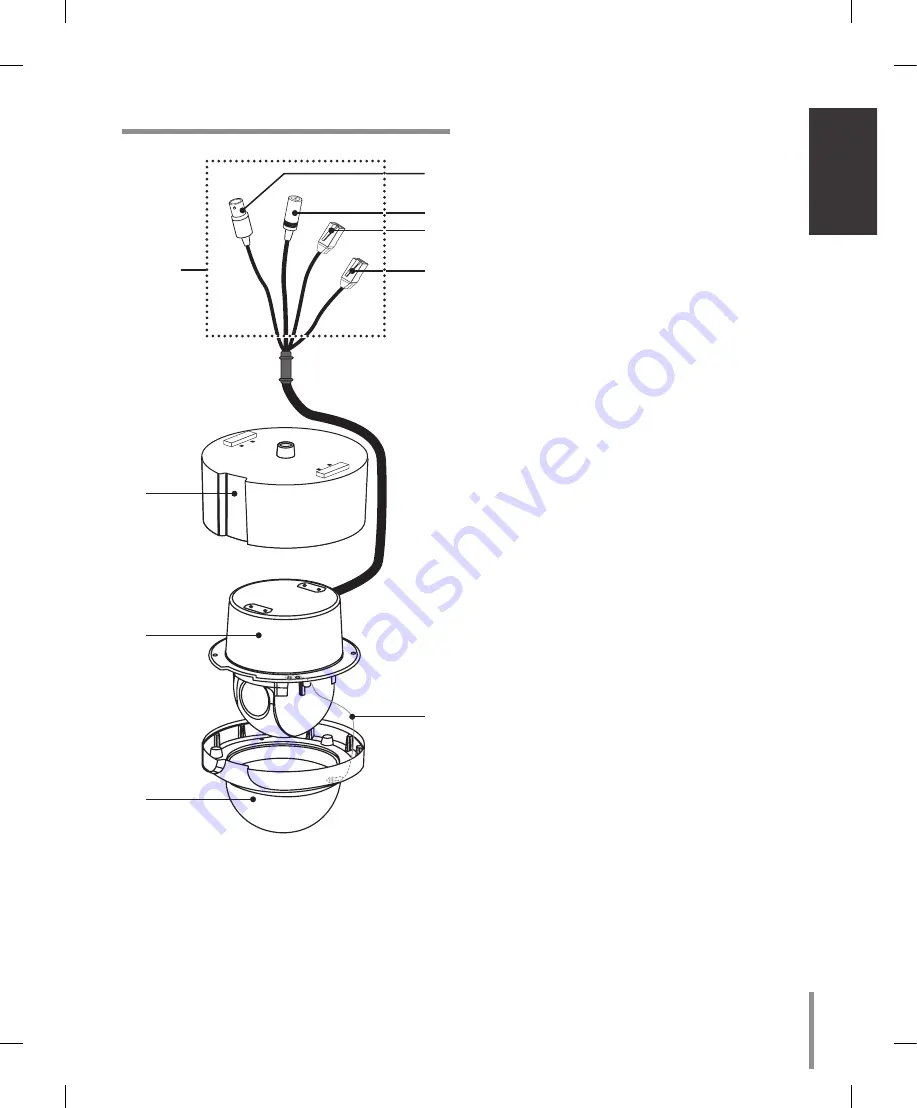
Identification of Camera

“A”

d

e
f

g

a

b

c

h

a

 Camera mounting bracket (Optional)

b

 Dome camera body

c

 Dome cover assembly

d

 Video output cable with BNC connector 

Connects with the video connector of the monitor.

e

 Power cable (DC 1V)

f

 Data Communication Port (RJ45) - RS-485 and 

Alarm Input

g

 Data Communication Port (RJ45) - RS-485 and 

Alarm Input

h

 Fall Prevention Wire

Be sure to hook the fall prevention wire into a 

bracket.

Caution: 

When you fix the dome cover to the dome camera 

body, you must insert the wire in the dome camera 

body. If not, the wire may obstruct the camera’s 

moving.

“A” 

Do not expose the power and data 

cable to moisture, this may cause leak-

age into the housing and damage the camera. If 

you must, please make sure that the connections 

are sealed tightly. After installing the camera, 

you should arrange the cables using the outlet 

box to protect the cables.

Summary of Contents for LT303NI

Page 1: ...Dome Camera Owner s Manual MODEL LT303PI LT303NI Before installing and using the camera please read this owner s manual carefully and retain for future reference ...

Page 2: ...gy and if not installed and used in accordance with the instruction manual may cause harmful interference to radio communications Operation of this equipment in a residential area is likely to cause harmful interference in which case the user will be required to correct the interference at his own expense A suitable conduit entries knock outs or glands shall be provided in the cable entries of thi...

Page 3: ...ruc tions 8 Do not install near any heat sources such as radiators heat registers stoves or other appa ratus including amplifiers that produce heat 9 Do not defeat the safety purpose of the polar ized or grounding type plug A polarized plug has two blades with one wider than the other A grounding type plug has two blades and a third grounding prong The wide blade or the third prong are provided fo...

Page 4: ... preview 15 RS 485 connection 15 Connecting monitor 15 Connecting power source 15 ALARM IN connections 15 Connecting LKD1000 controller 17 System Connection 18 Operation 19 Setup Menu Overview 19 Menu navigation 20 General Operation 21 Focus setting 21 Exposure settings 23 White Balance setting 24 Day Night setting 25 Motion Detection setting 25 Privacy Mask setting 26 3D DNR setting 26 Special me...

Page 5: ... setting is used for masking unwant ed zones hiding them from display on the monitor screen Up to 8 zones can be registered Auto Pan The camera has an Auto Pan function that enables to keep surveillance on every detail occurring around the specific area which is preset to watch in advance The camera can pan among the maximum 8 points you will set The moving speed and holding time are adjustable Au...

Page 6: ... solvents or detergents Use a dry cloth to the camera when it is dirty If it is hard to remove the dirt on the camera use a mild detergent and wipe it gently Do not install this camera upside down This camera is designed for mounting on the ceil ing or wall If you install this camera upside down for example mounted on the floor it may cause malfunction Do not use the camera in such places as shown...

Page 7: ...nd Alarm Input h Fall Prevention Wire Be sure to hook the fall prevention wire into a bracket Caution When you fix the dome cover to the dome camera body you must insert the wire in the dome camera body If not the wire may obstruct the camera s moving A Do not expose the power and data cable to moisture this may cause leak age into the housing and damage the camera If you must please make sure tha...

Page 8: ...and other locations where there are large amounts of steam vapor and oil in flammable atmospheres other special environ ments Areas where radiation X rays strong electric waves or magnetism is generated At sea in coastal areas or in areas where corro sive gas is being generated Areas outside of the allowable ambient operating temperature range When installing the camera on a ceiling of insuf ficie...

Page 9: ...y procured bracket Note The camera have not been evaluated for wall or ceil ing mounting Ceiling mount Ceiling Ceiling Surface mount Optional Note When you install the cam era to the ceiling mount you must drill a hole in the camera body as shown right ø5 0 Pendant mount Optional Install pipe and camera as shown below ...

Page 10: ...low B A Note Do not remove the block A to keep the gap B between the camera body and installation bracket B A How to install A Pipe threads should be clean and rust free Use a sealer such as Teflon tape and silicone sealer on the threads B A Add thread sealing tape Note The pipes and brackets for mounting are not supplied Reference Specifications of LG Standard pipe ...

Page 11: ... below 4 Power up the camera to load the changes SW101 Switch position SW101 Protocol ON ON ON ON Reserved 1 ON OFF ON ON LG Multix OFF ON ON ON Pelco D OFF OFF ON ON Pelco P ON ON OFF ON Reserved 2 OFF ON OFF ON Reserved 3 ON OFF OFF ON Reserved 4 OFF OFF OFF ON Reserved 5 ON ON ON OFF Reserved 6 OFF ON ON OFF Reserved 7 ON OFF ON OFF Reserved 8 OFF OFF ON OFF Reserved 9 ON ON OFF OFF Reserved 10...

Page 12: ... ON OFF OFF OFF 19 ON ON OFF OFF ON OFF OFF OFF 20 OFF OFF ON OFF ON OFF OFF OFF 21 ON OFF ON OFF ON OFF OFF OFF 22 OFF ON ON OFF ON OFF OFF OFF 23 ON ON ON OFF ON OFF OFF OFF 24 OFF OFF OFF ON ON OFF OFF OFF 25 ON OFF OFF ON ON OFF OFF OFF 26 OFF ON OFF ON ON OFF OFF OFF 27 ON ON OFF ON ON OFF OFF OFF 28 OFF OFF ON ON ON OFF OFF OFF 29 ON OFF ON ON ON OFF OFF OFF 30 OFF ON ON ON ON OFF OFF OFF 31...

Page 13: ...123 ON ON OFF ON ON ON ON OFF 124 OFF OFF ON ON ON ON ON OFF 125 ON OFF ON ON ON ON ON OFF 126 OFF ON ON ON ON ON ON OFF 127 ON ON ON ON ON ON ON OFF 128 OFF OFF OFF OFF OFF OFF OFF ON 129 ON OFF OFF OFF OFF OFF OFF ON 130 OFF ON OFF OFF OFF OFF OFF ON 131 ON ON OFF OFF OFF OFF OFF ON 132 OFF OFF ON OFF OFF OFF OFF ON 133 ON OFF ON OFF OFF OFF OFF ON 134 OFF ON ON OFF OFF OFF OFF ON 135 ON ON ON O...

Page 14: ...9 ON ON OFF ON ON OFF ON ON 220 OFF OFF ON ON ON OFF ON ON 221 ON OFF ON ON ON OFF ON ON 222 OFF ON ON ON ON OFF ON ON 223 ON ON ON ON ON OFF ON ON 224 OFF OFF OFF OFF OFF ON ON ON 225 ON OFF OFF OFF OFF ON ON ON 226 OFF ON OFF OFF OFF ON ON ON 227 ON ON OFF OFF OFF ON ON ON 228 OFF OFF ON OFF OFF ON ON ON 229 ON OFF ON OFF OFF ON ON ON 230 OFF ON ON OFF OFF ON ON ON 231 ON ON ON OFF OFF ON ON ON ...

Page 15: ...5 site communication Shielded twisted pair cable Low impedance Wire gauge size is thicker than AWG 22 0 33 mm2 Connecting monitor The video signal connection between the camera and the monitor Connecting power source Connect a DC 12 V power source to the power input terminal ALARM IN connections Connect external sensors to the 8 pin haness connec tor Each alarm sensor should be connected with G GN...

Page 16: ...nsed position There are Manual mode and Auto mode for the Alarm Input function Manual mode Change the observe position to a sensor that senses a touch or shock then keep observe the sensed position Set the Duration Time of Alarm Input function to 0 using the LKD1000 controller Example If this unit receives signal from Alarm 4 Preset 1 Preset 2 Preset 3 Alarm 1 Alarm 2 Alarm 3 Preset 4 Alarm 4 Alar...

Page 17: ...on status Auto mode While observe a specific position Change the observe position to the alarmed position then return to the position that previously observed While operating Preset Tour func tion Stop preset touring and change the observe position to the alarmed position then restart the preset touring again While operating Auto Pan func tion Stop auto panning and change the observe position to t...

Page 18: ...D Yellow TX TX System Connection Note When any peripheral is turned off and turned on again the camera is also turned off and turned back on Caution Do not connect the alarm connectors to the another camera s alarm connectors Caution Connect the supplied termination adapter to the final camera s data port to prevent the RS 485 communi cation error Controller or ...

Page 19: ...C HSBLC BRIGHTNESS 0 100 SHUTTER X512 x2 AUTO OFF A FLK 1 160 1 90000 SENS UP OFF AUTO x2 AUTO x128 INITIAL SET EXIT RET TOP END WHITE BALANCE ATW AUTO ONE PUSH MANUAL COLOR TEMP INDOOR OUTDOOR RED 100 100 BLUE 100 100 INITIAL SET EXIT RET TOP END Main Menu Sub Menu Contents DAY NIGHT AUTO D N LEVEL LOW MIDDLE HIGH DWELL TIME 5 10 15 30 60 sec INITIAL SET EXIT RET TOP END DAY NIGHT MOTION DET OFF ...

Page 20: ...navigation We use the LKD1000 controller in this manual to explain the features of the LG Dome camera because of the LKD1000 s ability to control all of the LG Dome camera s advanced features For detailed controller instructions refer to the LKD1000 Controller Manual Buttons Function Cam OSD button Displays the setup menu or cancels operation of the setup menu ZOOM IN button Use to move upper dire...

Page 21: ... Select EXIT option then press Open or Close to exit the setup menu In the submenu use In or Out button to select the EXIT then use Near or Far button to select a mode and press Open or Close to exit the setup menu RET Return to the previous TOP Return to the CAMERA SETTING menu screen END Exit the setup menu Focus setting Focus Mode setting The camera adjusts the focus automatically by sens ing t...

Page 22: ...et the zoom end position of the camera If you set the zoom end position the zoom is operated up to the selected zoom end position Select ZOOM END option on the FOCUS menu then set the zoom end position Zoom Start posi tion 1 x324 Zoom Speed setting Selects a zoom speed Select ZOOM SPEED option on the FOCUS menu then select a zoom speed SLOW MIDDLE or QUICK Zoom Tracking Mode setting Selects a zoom...

Page 23: ...the BLC limit BLC LEVEL LOW y MIDDLE y HIGH HSBLC Use for adjusting brightness the specific area of picture The HSBLC mode is automatically activated only in low illuminance scene AREA SETTING Use Near or Far but ton to select a area then use In or Out button to select a ON or OFF Press Open or Close to exit the area setting menu GRAY SCALE Use Near or Far button to select a gray scale GRAYyD GRAY...

Page 24: ...e color of a light source 1 Select WHITE BALANCE option on the CAMERA SET menu 2 Use Near or Far button to select a mode then press Open or Close ATW Auto Tracing White Balance In this mode the color temperature range for the proper white balance is approximately 1 800 10 500 K Proper white balance may not be obtained under the following conditions When the color temperature is out of the 1 800 10...

Page 25: ...able and mark is displayed DAY Color mode enabled NIGHT Black and white mode enabled Motion Detection setting The motion detection detects the moving objects in the scene by monitoring changes in brightness level You can select the level of sensitivity for motion detec tion to 4 zone 1 Select MOTION DET option on the CAMERA SET menu 2 Use Near or Far button to select a ON and press Open or Close T...

Page 26: ...Out to select an option then use Near or Far button to adjust the option WIDTH Enlarge or decrease the horizontal size of the mask zone box HEIGHT Enlarge or decrease the vertical size of the mask zone box MOVE X Moves horizontal position of the mask zone box MOVE Y Moves vertical position of the mask zone box Notes If you want to reset the mask zone position select RESET MASK option and press Ope...

Page 27: ...t the option If you set the sharpness value to higher the image outline becomes sharp If you set to lower value the image outline becomes dim Stabilizer setting The image stabilizer function minimizes the appear ance of shaky images caused by low frequency vibra tion This function is useful for outdoor surveillance Select STABILIZER option and set to ON or OFF Note If you set the STABILIZER to ON ...

Page 28: ...ong code select CLR then press Open or Close POS Use Near or Far button to move posi tion of USER TITLE on the screen END Confirm your selection A Blank Insert a space at the cursor posi tion Moves cursor to left or right Language setting Select a language for setup menu and information display Reset settings 1 Select RESET option 2 Press Open or Close button and the RESET menu appears 3 Use In or...

Page 29: ...K 10 500 ºK Video Output Composite Output 1Vp p 75 ΩTerminated Electronic Shutter 1 60 1 90 000 sec 1 50 1 90 000 sec Electronic Sensitivity OFF Auto x2 x3 x4 x 128 Flickerless Mode Available Iris Control Auto Manual Control method RS 485 Control Alarm Input 4 Channel Panning Range Speed 0º 350º Max 120º Sec Tilting Range Speed 0º 180º Max 120º Sec Privacy Zone 8 Area Active Programmable Zone Pres...

Page 30: ......

Page 31: ......

Page 32: ...P NO MFL62034797 ...

Reviews: