background image

3-5

Copyright © 

 LG Electronics Inc. All rights reserved.

Only training and service purposes

COMPONENT ACCESS

1.  Turn off the electrical supply and gas supply going 

to the range.

2.  Remove the cooktop plate (See “REMOVING 

THE COOKTOP PLATE” on page 3-4).

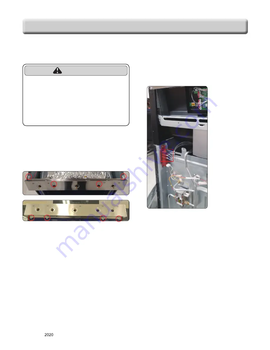
3.  Remove the manifold panel by unfastening the 8 

screws.

4.  Remove rear cover & motor cover (See step 3~4 

on page 3-2) 

5. Disconnect 5 connectors.

REMOVING THE CASE ASSEMBLY 

(COOKTOP BURNER ASSEMBLY)

 WARNING

•  DISCONNECT power supply cord 

from the outlet before servicing.

•  Replace all panels and parts before 

operating.

•  RECONNECT all grounding devices.

-  Failure to do so can result in severe personal 

injury, death or electrical shock.

Summary of Contents for LRGL5821S

Page 1: ... or other electronic means publication modification copying or transmission of this Service Manual is STRICTLY PROHIBITED unless you have obtained the prior written consent of the LG Electronics entity from which you received this Service Manual The material covered by this prohibition includes without limitation any text graphics or logos in this Service Manual Copyright 2020 LG Electronics Inc A...

Page 2: ...epairs made on our products by anyone other than Authorized Service Technicians WARNING WARNING DISCONNECT power supply cord from the outlet before servicing Replace all panels and parts before operating RECONNECT all grounding devices Failure to do so can result in severe personal injury death or electrical shock DO NOT Touch when the oven operates The interior parts will be very hot Never Operat...

Page 3: ...anging hour mode on clock 12HR 24HR Auto Conversion COMPONENT ACCESS 3 1 3 21 Component Locations 3 1 Removing the Back Control cover and Key pad assembly 3 2 Removiing Power Control Board PCB 3 3 Removiing the Cooktop Plate and the Spark Module 3 4 Removing the Case assembly Cooktop Burner assembly 3 5 Removing the Cooktop Parts 3 6 3 7 Removing the BROIL Burner assembly 3 8 Oven Bottom the Frame...

Page 4: ...5 1 5 5 COMPOSITION OF CONTROL 6 1 6 2 Main PCB 6 2 Tact Display PCB 6 2 LED Module 6 2 DIAGNOSIS THROUGH SCHEMATIC 7 1 CHECK THE FAILURE CODE F code 8 1 FAILURE CODE SUMMARY 9 1 CHECKING FLOW CHART BY FAILURE 10 1 10 22 No display No power 10 1 10 4 No heating including F9 error 10 5 10 8 Sensing fail including F1 F2 error 10 9 10 11 Oven hot including F6 error 10 12 10 14 No Key input 10 15 Oven...

Page 5: ...ating RECONNECT all grounding devices Failure to do so can result in severe personal injury death or electrical shock DO NOT touch burners grates or interior surfaces of oven Heating element may be hot even though they are off Interior surfaces of an oven become hot enough to cause burns During and after use do not touch or let clothing or other flammable materials contact burners grates or interi...

Page 6: ... after use do not touch or let clothing or other flammable materials contact burners grates or interior surfaces of oven until they have had sufficient time to cool Other surfaces of the appliance may become hot enough to cause burns among these surfaces are oven vent openings and surfaces near these openings oven doors and windows of oven doors WARNING DO NOT store items of interest to children i...

Page 7: ...in temperature Utensil Handles Should Be Turned Inward and Not Extend Over Adjacent Surface Units To reduce the risk of burns ignition of flammable materials and spillage due to unintentional contact with the utensil the handle of a utensil should be positioned so that it is turned inward and does not extend over adjacent surface units Be sure you know which knobs operate each burner Make sure you...

Page 8: ...ts reserved Only training and service purposes GENERAL The Model Serial Number label and Tech Sheet locations are shown below Model Serial Number Location MODEL SERIAL NUMBER LABEL AND TECH SHEET LOCATIONS Tech Sheet Location On Low Rear Cover ...

Page 9: ...eheating alarm light 4 Set the beeper volume Hi Lo Off 5 Switch the temperature scale between Fahrenheit and Celsius Cooktop Material Enamel of element 5 Input Rate NAT LP BTU hr LR 9 1k 9 1k RR 5k 5k CR 10k 10k LF 12k 10k RF 17k 12k Oven Capacity cu ft 5 8 Broil NAT LP BTU hr 13 5k Bake BTU hr 19k 18k Convection system No of Racks 2 standard Interior oven light auto manual Proof No Cook warm No F...

Page 10: ...lacement parts Functional Operation Bake Mode Bake burner operates during bake mode Bake can be used to cook foods which are normally baked Oven must be preheated Broil Mode Broil burner operates during broil mode Broil can be used to cook foods which are normally broiled Preheating is not required when using broil All foods should be turned at least once except fish which does not need to be turn...

Page 11: ...cs Inc All rights reserved Only training and service purposes USING YOUR RANGE CONTROL PANEL FEATURES 2 1 4 5 6 3 1 Features 2 Oven Controls 3 Number Buttons or Buttons 4 Start Button 5 Clear Off Lockout Button 6 Smart Diagnosis ...

Page 12: ... center is for large pots pans or for use with the griddle 2 SETTING THE CLOCK 3 START CLEAR OFF 1 Touch START key to start oven 2 Touch CLEAR OFF key to cancel a program during cooking or Erase during programming 4 TO TURN ON OFF THE OVEN LIGHT The oven light automatically turns ON when the door is opened 1 The oven light may also be manually turned ON or OFF by press the OVEN LIGHT pad 2 Knockin...

Page 13: ...e change 9 TEMPERATURE UNIT F or C 1 Press Settings repeatedly until Unit appears in the display 2 Press 1 to select F Fahrenheit or C Celsius 3 Press Start to accept the change 10 BAKE TIMED BAKE 11 BROIL 12 TIMED COOK WITH WARM 13 CHANGING HOUR MODE ON CLOCK 12HR 24HR 14 AUTO CONVERSION BAKE Desired Temp COOK TIME Desired time WARM START Press and hold the Settings button for 3 seconds Press 1 t...

Page 14: ...in PCB Burner body Cooktop valve Bake burner Ignition switch Broil burner Burner pipe Igniter broil Oven light Oven sensor Igniter bake Door switch Spark module COMPONENT ACCESS This section instructs you on how to service each component inside the range The components and their locations are shown below COMPONENT LOCATIONS ...

Page 15: ... Eye brow 7 Remove the 7 screws on the controller assembly and remove the assemblies in order 1 2 2 8 Replace the control panel assembly Main PCB 5 Separate PCB assembly after unplugging the 6 connectors REMOVING THE BACK CONTROL COVER AND KEY PAD ASSEMBLY WARNING DISCONNECT power supply cord from the outlet before servicing Replace all panels and parts before operating RECONNECT all grounding dev...

Page 16: ... 4 on page 3 2 4 When you check PCB check the proper pcb in default mode and check main pcb NOTE Refer to the page 6 1 6 2 for composition of control board Main PCB WARNING DISCONNECT power supply cord from the outlet before servicing Replace all panels and parts before operating RECONNECT all grounding devices Failure to do so can result in severe personal injury death or electrical shock CAUTION...

Page 17: ...ner housings 4 Disengage 2 front clips using a steel ruler REMOVING THE COOKTOP PLATE AND THE SPARK MODULE WARNING DISCONNECT power supply cord from the outlet before servicing Replace all panels and parts before operating RECONNECT all grounding devices Failure to do so can result in severe personal injury death or electrical shock 5 Life top up at front NOTE Before lowering the top onto the fron...

Page 18: ... on page 3 4 3 Remove the manifold panel by unfastening the 8 screws 4 Remove rear cover motor cover See step 3 4 on page 3 2 5 Disconnect 5 connectors REMOVING THE CASE ASSEMBLY COOKTOP BURNER ASSEMBLY WARNING DISCONNECT power supply cord from the outlet before servicing Replace all panels and parts before operating RECONNECT all grounding devices Failure to do so can result in severe personal in...

Page 19: ...r supply cord from the outlet before servicing Replace all panels and parts before operating RECONNECT all grounding devices Failure to do so can result in severe personal injury death or electrical shock CAUTION The 2 lock tabs on each igniter switch are fragile Tab breakage can occur if excessive release pressure is applied Check that the gas seal gasket on the screw and the gas valve remain in ...

Page 20: ...3 7 Copyright LG Electronics Inc All rights reserved Only training and service purposes COMPONENT ACCESS 5 To remove the electrode spark plug a Remove the electrode from the burner housing ...

Page 21: ...der for easily removing d 1 d 4 d 2 d 3 c 1 d 5 NOTE When removing the screws make sure holding the Broil burner assembly 4 To remove the igniter a Perform step 1 3 on this page b Remove the 2 screws and then remove the igniter 2 screws WARNING DISCONNECT power supply cord from the outlet before servicing Replace all panels and parts before operating RECONNECT all grounding devices Failure to do s...

Page 22: ... behind 4 Remove the oven door and racks from inside of the oven 5 To remove the oven bottom Remove the 2 screws and then remove oven bottom 2 screws 6 To remove the flame guide Remove the 4 screws and then remove flame guide 4 screws 7 To remove the bake burner assembly Remove the 2 screws and then remove the burner assembly 2 screws 8 To remove the igniter Remove the 2 screws and then remove the...

Page 23: ...liner hole and pull the socket out of the liner NOTE If it is too difficult to remove the socket from the front of the oven you will have to push the socket out from the back of the unit Socket Clips 6 Disconnect the wires from the socket terminals Viewed From Rear Panel CAUTION Be careful not to scratch or chip the oven liner paint when you remove the oven light socket in the next step WARNING DI...

Page 24: ...ews b Remove rear cover motor cover See step 3 4 on page 3 2 c Disconnect the wire connection d Remove the oven sensor WARNING DISCONNECT power supply cord from the outlet before servicing Replace all panels and parts before operating RECONNECT all grounding devices Failure to do so can result in severe personal injury death or electrical shock CAUTION Be careful when you work on the gas range han...

Page 25: ...r Replacing the Drawer 1 Place the drawer rails on the guides 2 Push the drawer back until it stops 3 Lift the front of the drawer and push back until the stops clear the guides 4 Lower the front of the drawer and push back until it closes CAUTION Disconnect the electrical power to the range at the main fuse or circuit breaker panel Failure to do so can result in severe personal injury death or el...

Page 26: ...ity to the locked position 5 Close the oven door To remove the door 1 Fully open the door 2 Pull the hinge locks up toward Fig 1 the door frame to the unlocked position 3 Firmly grasp both sides of the door at the top 4 Close door to the door removal position which is approximately 5 degrees refer to the Fig 2 5 Lift door up and out until the hinge arm is clear of the slot Slot Hinge lock Lock Unl...

Page 27: ...or liner 7 screws 5 Lift the liner assembly off the front glass and set it aside 6 To remove the door handle trim Remove the 2 door handle screws and lift the door handle off door trim and slide up the door trim Door handle screw WARNING DISCONNECT power supply cord from the outlet before servicing Replace all panels and parts before operating RECONNECT all grounding devices Failure to do so can r...

Page 28: ...ee step 3 4 on page 3 17 b Place the door liner assembly on a padded work surface with the hinge hangers over the edge c Remove the 4 top door screws d Lift the hinge hanger out of the door liner slot 4 top liner Screws 8 Lift the insulation cover inner oven door glass and bracket assembly out of the door liner Door frame Hinge Insulation cover Inner oven door Glass Bracket ...

Page 29: ...s are removed 3 Pull the ends of the gasket out of the liner holes Door gasket Gasket clip 2 Liner Hole 3 WARNING DISCONNECT power supply cord from the outlet before servicing Replace all panels and parts before operating RECONNECT all grounding devices Failure to do so can result in severe personal injury death or electrical shock CAUTION Be careful when you work on the gas range handling the she...

Page 30: ...16 for the procedure 3 Pull the range away from the wall so you can access the back of the unit 4 Remove the rear panel see page 3 2 5 Raise the cooktop plate see the page 3 4 for the procedure 6 Remove the two screws from the top rear of the side panel WARNING DISCONNECT power supply cord from the outlet before servicing Replace all panels and parts before operating RECONNECT all grounding device...

Page 31: ...g devices Failure to do so can result in severe personal injury death or electrical shock CAUTION Be careful when you work on the gas range handling the sheet metal part Sharp edge may be present and you can cut yourself 1 Turn off the electrical supply and gas supply going to the range 2 To remove the rear panel a Pull the range away from the wall so you can access the pipe of the unit b Remove t...

Page 32: ... far enough 3 Resistance checks must be made with power cord unplugged from outlet and with wiring harness or connectors disconnected Before testing any of components perform the following checks WARNING Turn off the electrical supply and gas supply going to the range Replace all panels and parts before operating Reconnect all grounding devices after servicing Failure to do so can result in death ...

Page 33: ...ximately 1 09 kΩ 10 If not replace NOTE Ω Value was tested at room temperature 77F 25 C NOTE Oven sensor is so sensitive to temperature Do test after cooling down sufficiently Door switch 1 Refer to page 3 8 for the servicing procedure 2 Measure the resistance after cooling down Multiple meter scale R x 1 Door open Door closed Continuity Infinite Oven lamp 1 Measure the resistance after cooling do...

Page 34: ...l 45 Ω 400 Ω Room Temperature Resistance If not replace Oven safety valve 1 Refer to page 3 21 for servicing procedure 2 Measure the resistance after cooling down Multiple meter scale R x 1 Upside Downside Normal Approximately 1 3 Ω If not replace Ignition switch 1 Refer to page 3 6 3 7 for servicing procedure 2 Measure the resistance by rotating the cam of each switch slowly Multiple meter scale ...

Page 35: ...ly going to the range Replace all panels and parts before operating RECONNECT all grounding devices Failure to do so can result in severe personal injury death or electrical shock CAUTION Be careful when you work on the gas range handling the sheet metal part Sharp edge may be present and you can cut yourself 2 CONVERT THE PRESSURE REGULATOR WARNING Do not remove the pressure regulator from the ra...

Page 36: ...U HR Natural Gas 5 W C P MODEL BURNER BTU RATE ORIFICE CODE LRGL5825 LRGL5823 LRGL5821 LF 17 000 12 000 12 000 190 155 155 LR 9 100 134 RR 5 000 102 RF 20 000 20 000 17 000 208 208 190 CTR 10 000 142 BROIL 13 500 P BAKE 19 000 A K 208 Top burner orifices Broil and Bake burner orifices Denotes orifice code WARNING Turn off the electrical supply and gas supply going to the range Replace all panels a...

Page 37: ...ock CAUTION Be careful when you work on the gas range handling the sheet metal part Sharp edge may be present and you can cut yourself 4 To prevent leakage make sure the orifice spuds are securely screwed into the gas supply tubes 5 Put the old orifice spuds into conversion kits and place back on the range for possible future conversion NOTE If an orifice spud is accidentally dropped the cooktop p...

Page 38: ...orifce spud F to the nozzle holder To prevent leakage make sure the orifice spud is securely screwed into the nozzle holder Counterclockwise to remove Clockwise to install 6 Turn on the Electrical and Gas Supply to continue with flame adjustment 7 ADJUSTING THE AIR SHUTTER For bake burner adjust the Air Shutter for LP gas loosen the Philips head screw and rotate the shutter to the fully open posit...

Page 39: ... all orifice s that were removed for natural gas back into the plastic bag along with the instructions Place the kit back into its original location CONVERSION IS FINISHED To convert to the original gas Follow conversion process with original orifices to convert the appliance to the original gas WARNING Turn off the electrical supply and gas supply going to the range Replace all panels and parts b...

Page 40: ...6 1 Copyright LG Electronics Inc All rights reserved Only training and service purposes COMPOSITION OF CONTROL Front Back Controller assembly Main PCB Tact Display PCB ...

Page 41: ...6 2 Copyright LG Electronics Inc All rights reserved Only training and service purposes Main PCB COMPOSITION OF CONTROL Tact Display PCB LED Module ...

Page 42: ...MBOL COLOR WH WHITE BK BLACK RD RED YL YELLOW PK PINK BL BLUE BN BROWN GN GREEN GY GRAY OR ORANGE VI VIOLET Symptom Sensor error or no heating F 1 F 2 F 9 Check Sensor resistance approximately 1 06 kΩ at 65F 1 12 kΩ at 85F Symptom Oven lamp not operating Check the Lamp coil s resistance Normal approximately 20 40Ω Symptom Oven hot F 6 Check All heater relays are open short ...

Page 43: ...ure code as below steps 1 press the clear key 2 press the BAKE and BROIL key at the same time for 1 second If the oven has some failure the oven will show the failure code like FIG 1 It shows the type of F code and times of failure alternately for each two seconds If the oven does not have any failure the oven will display like FIG 2 NOTE After checking the failure code press the CLEAR key FIG 2 F...

Page 44: ...ver 1 min during cooking 1 Wiring 2 Oven Sensor F 3 Key shorted Error When some keys are continuously short for over 60 seconds Key malfunction F 6 Oven hot The oven temperature is over 650 F continuously during 2 minutes on cooking except self cleaning 1 Oven Sensor 2 Relay F 9 No heating If starting oven temperature does not exceed 150 F and oven temperature is less Than or equal to starting tem...

Page 45: ...yright LG Electronics Inc All rights reserved Only training and service purposes CHECKING FLOW CHART BY FAILURE Symptom Check Point 1 Power Failure Dead 2 No Display 1 Check Electric Wiring 2 Check the Main PCB ...

Page 46: ...Check the connection of Main PCB CN01 Nomal Yes No Yes Plug the unit Power Failed Dead No display Check the button beep Touch the Clear button Can hear the beep sound Go to 7 On the next Page No Reconnect If defective harness replace or fix 1 No Yes Check the connection of Power Cord Normal Reconnect If defective harness replace or fix 2 3 ...

Page 47: ... CHART BY FAILURE Check the AC input of Main PCB Main PCB 1pin 3pin of CN01 120V AC No Yes Replace the main PCB 4 No Yes Check the connection of L1 and N at Terminal block Normal Reconnect 5 No Yes Check the Thermostat Normal Short Abnormal Open Normal Replace the Thermostat Replace the main PCB 6 CN01 ...

Page 48: ...ECKING FLOW CHART BY FAILURE Check the connection States between CN21 of Main PCB and Display PCB Is it OK No Yes Replace the Main PCB 7 Reconnect If defective harness replace or fix If the same phenomenon occurs even though after fixed connection you should replace the Display PCB CN21 CN21 ...

Page 49: ...s Inc All rights reserved Only training and service purposes CHECKING FLOW CHART BY FAILURE Symptom Check Point 1 No heating 2 F9 1 Check Electric Wiring 2 Check Heater s Resistance 3 Check the Sensor thermistor TAB01 06 CN10 CN10 ...

Page 50: ...service purposes CHECKING FLOW CHART BY FAILURE Oven does not heat Oven does NOT heat Is the Connector disconnected or loose 1 Electric wiring of Relay PCB All taps 2 Electric wiring of electric element Yes Reconnect If defective harness Replace or fix 1 Unplug the unit No ...

Page 51: ...All rights reserved Only training and service purposes CHECKING FLOW CHART BY FAILURE Check the resistance of each heater Normal Measure the resistance after cooling down The resistance is shown below No Replace the failed heater 2 Yes ...

Page 52: ...training and service purposes CHECKING FLOW CHART BY FAILURE Is the resistance of thermistor normal Check Pin 1 and 2 of CN10 in main PCB Normal approximately 0 6 1K ohm at 25 No Replace the defective Thermistor 4 Yes Unplug the unit CN10 5 Replace the Main PCB ...

Page 53: ...lectronics Inc All rights reserved Only training and service purposes CHECKING FLOW CHART BY FAILURE Symptom Check Point 1 Sensing Fail 2 F 1 3 F 2 1 Check the electric wiring 2 Check the sensor thermistor resistance CN10 ...

Page 54: ... and service purposes CHECKING FLOW CHART BY FAILURE Main oven sensing error F 1 F 2 error Is the Connector disconnected or loose 1 Sensor connection 2 CN10 of Main PCB Yes Reconnect or adjust the connection 1 No Unplug the unit CN10 Sensor connection Sensing Fail F1 F2 ...

Page 55: ...service purposes CHECKING FLOW CHART BY FAILURE Main oven sensing error F 1 F 2 error No Replace the defective Thermistor 2 Yes CN10 Is the resistance of thermistor normal Check Pin 1 and 2 of CN10 of Main PCB Normal approximately 0 6 1K ohm at 25 2 1 3 Replace the Main PCB ...

Page 56: ...10 12 Copyright LG Electronics Inc All rights reserved Only training and service purposes CHECKING FLOW CHART BY FAILURE Symptom Check Point 1 Oven hot 2 F 6 1 Check the Resistance of the Relay TAB04 08 ...

Page 57: ...ed Only training and service purposes CHECKING FLOW CHART BY FAILURE Oven too hot error F 6 error Check the DLB Relay damage measure the resistance Yes Replace the Main PCB 1 No Unplug the unit F6 Oven Hot Normal Abnormal Continuity Infinite TAB11 TAB12 ...

Page 58: ...ining and service purposes CHECKING FLOW CHART BY FAILURE Oven too hot error F 6 error No Replace the Main PCB 2 Yes Is the resistance of thermistor normal Check Pin 1 and 2 of CN10 of Main PCB Normal approximately 0 6 1K ohm at 25 3 Replace the Thermistor CN10 2 1 ...

Page 59: ...URE Key does not input Check the oven lock operation Nomal unlock No key input END END END No No Yes Yes Cancel the Door locking press the start key for three seconds Normal No Yes Replace the PCB Case or Display PCB Replace the main PCB Normal Normal Check the control panel and Find the mechanical malfunction of key ...

Page 60: ...he looseness of oven lamp terminal and harness Check the looseness of connector TAB04 and 7pin of CN02 END No No Yes Normal Yes Normal Oven lamp does not operate Disconnect the power Oven lamp does not operate Reconnect In case of the defective harness replace or fix Reconnect END Welded Normal Continuity Infinite NO COM NO COM ...

Page 61: ...aining and service purposes CHECKING FLOW CHART BY FAILURE Oven lamp does not operate Yes Normal No Check the oven lamp measure the resistance Normal approximately 20 40Ω Abnormal infinite Replace the oven lamp Replace the Main PCB END END Abnormal Infinite NO COM ...

Page 62: ...e cabinets are square and have sufficient room for range clearance Top burners do not light or do not burn evenly The plug on range is not completely inserted in the electrical outlet Burner slits on the side of the burner may be clogged Improper burner assembly Make sure the electrical plug is inserted into a live properly grounded outlet Remove the burners and clean them Check the electrode area...

Page 63: ...ou touch the BROIL HI LO pad See the USING THE OVEN section in user s guide See the BROILING GUIDE in user s guide Use the broiling pan and grid that came with your range Make sure it is cool Use the broiling pan and grid that came with your range See the USING THE OVEN section in user s guide Moisture collects on oven window or steam comes from oven vent When cooking foods high in moisture Excess...

Page 64: ...r towel Do not use lubricant sprays Power outage clock flashes Power outage or surge Reset the clock If the oven was in use you must reset it by touching the CLEAR OFF pad setting the clock and resetting any cooking function Burning or oily odor emitting from the vent This is normal in a new oven and will disappear in time To speed the process set a self clean cycle for a minimum of 3 hours See th...

Page 65: ... Electronics Inc All rights reserved Only training and service purposes EXPLODED VIEW EV MODEL Customer Model Product Code SVC Model INTRODUCTION DOOR PARTS DRAWER PARTS COOKTOP PARTS CONTROLLER PARTS CAVITY PARTS ...

Page 66: ...LG Electronics Inc All rights reserved Only training and service purposes DOOR PARTS EV 1020 1009 1021 1733 1466 1704 W321 1704 1733 W101 W321 1735 102L 102S W101 W108 102S 102U 1000 W243 W225 W225 W222 1801 1028 ...

Page 67: ...Copyright LG Electronics Inc All rights reserved Only training and service purposes CONTROLLER PARTS EV 2381 2034 2501 3075 2006 2037 W227 2036 W144 H212 H211 H213 3006 2374 2050 ...

Page 68: ...d Only training and service purposes EV COOKTOP PARTS 3945 3990 3977 7384 3979 3971 3978 3972 3976 3974 3975 3973 W294 W294 3056 3925 W227 555C 3961 3964 3962 5947 5949 5948 3982 5950 3982 3981 3981 3960 3961 3940 2441 3946 3945 3986 W323 5946 3981 ...

Page 69: ...Copyright LG Electronics Inc All rights reserved Only training and service purposes DRAWER PARTS EV 8514 8501 8507 3541 3541 3036 851D 851D 8530 8524 850R 850L 8530 8508 8503 8603 ...

Page 70: ...RTS 5912 5944 5942 5941 5900 W301 W115 5539 5517 5905 8550 5904 5903 5955 5462 2058 5509 5032 5922 5911 4002 5511 2048 5510 5515 3501 5958 W290 5463 5021 W301 5952 5900 5943 5931 5409 5452 9384 5516 W230 5512 5532 W230 5512 5533 5010 8511 W229 9381 5014 W225 W225 5019 3013 3063 3013 3063 5556 5556 ...

Page 71: ......

Reviews: