background image

8

Installation

Precautions

• The following steps of installation and connection

work should be done by qualified service person-
nel or system installers and should conform to all
local codes.

• Be sure to switch the camera off before installation

and connection.

• Do not install the camera near the air outlet of an

air conditioner.

• Do not touch the dome cover’s window.

Removing the Protection Tape

Before using the camera, remove the protection tape. 

Caution: 

Remove the protection tape carefully.

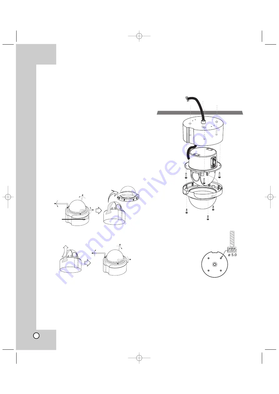
1. Loosen the screws using the wrench and remove

the dome cover as shown below.

2. Remove the protection tape and attach the dome

cover.

Mounting the Camera

The figures show an example of the camera mounted
on a ceiling or wall with a locally procured bracket.
Refer to the instructions included with the bracket for
filling gaps and holes with waterproof material.

Note:

When you install the
camera to the ceiling
mount, you must drill

a hole in the camera

body as shown right.
(ø5.0)

The Ceiling

The Ceiling

Protection

tape.

Surface mount

LPT-OS553HQ_ENG_6602  7/19/07  2:08 PM  Page 8

Summary of Contents for LPT-OS551HQ

Page 1: ...amera Owner s Manual MODEL LPT OS551HQ LPT OS553HQ Before installing and using the camera please read this owner s manual carefully and retain for future reference LPT OS553HQ_ENG_6602 7 19 07 2 08 PM Page 1 ...

Page 2: ...according to the manufacturer s instructions Holes in metal through which insulated wires pass shall have smooth well rounded surfaces or shall be provided with brushings Warning Do not install this equipment in a confined space such as a bookcase or similar unit Warning Wiring methods shall be in accordance with the National Electric Code ANSI NFPA 70 Warning This is a class A product In a domest...

Page 3: ...hird grounding prong The wide blade or the third prong are provided for your safety If the provided plug does not fit into your outlet consult an electrician for replacement of the obsolete outlet 10 Protect the power cord from being walked on or pinched particularly at plugs convenience recepta cles and the point where they exit from the apparatus 11 Only use attachments accessories specified by ...

Page 4: ...era incorporates the digital signal processor pan tilt mechanism x27 zoom lens and RS 485 com munication interface in a compact outdoor enclosure A newly developed 1 4 CCD makes the camera suitable for use under extremely low illumination con ditions as well as in daylight Setup menus allow the camera to perform surveil lance tasks by such means as digital flip pattern recording and privacy zones ...

Page 5: ...s capable of capturing a subject by the focus of camera moving promptly toward the subject at the rate of 120 sec when the camera works with a detector magnetic beam infrared rays and a subject moving within a detection area is captured by a detector x x Alarm In function Alarm input signals are supplied from external devices through the ALARM IN connector to turn the camera to a preset position x...

Page 6: ...l this camera upside down for example mounted on the floor it may cause malfunction x x Do not use the camera in such places as shown below The lens may become cloudy due to condensation if the camera is used under the following condi tions Rapid temperature fluctuation by switching an air conditioner on and off Rapid temperature fluctuation due to frequent door opening and closing Use in an envir...

Page 7: ... RS 485 and Alarm Input 7 Data Communication Port RJ45 RS 485 and Alarm Input 8 Fall Prevention Wire Be sure to hook the fall prevention wire into an bracket Identification of Camera 1 2 3 4 8 5 6 7 A A Do not expose cable connection part to outdoor such as rain moisture environment It may cause waterproof problem But If you are indeed Sealing them tightly LPT OS553HQ_ENG_6602 7 19 07 2 08 PM Page...

Page 8: ...tection tape Caution Remove the protection tape carefully 1 Loosen the screws using the wrench and remove the dome cover as shown below 2 Remove the protection tape and attach the dome cover Mounting the Camera The figures show an example of the camera mounted on a ceiling or wall with a locally procured bracket Refer to the instructions included with the bracket for filling gaps and holes with wa...

Page 9: ...nd rust free Use a sealer such as Teflon tape or silicone sealer on the threads Add thread sealing tape Reference Specifications of LG Standard pipe Note Do not remove the block A to keep the gap B between the camera body and installation bracket A B LPT OS553HQ_ENG_6602 7 19 07 2 08 PM Page 9 ...

Page 10: ...N Reserved 5 OFF OFF OFF ON Reserved 6 ON ON ON OFF Reserved 7 OFF ON ON OFF Reserved 8 ON OFF ON OFF Reserved 9 OFF OFF ON OFF Reserved 10 ON ON OFF OFF Reserved 11 OFF ON OFF OFF Reserved 12 ON OFF OFF OFF Reserved 13 OFF OFF OFF OFF Reserved 14 ON 1 2 3 4 ON OFF SW104 ON 1 2 3 4 ON OFF 1 2 ON 1 2 3 4 ON 1 2 3 4 ON 1 2 3 4 ON 1 2 3 4 ON 1 2 3 4 ON 1 2 3 4 ON 1 2 3 4 ON 1 2 3 4 ON 1 2 3 4 ON 1 2 ...

Page 11: ...F OFF OFF OFF 12 OFF OFF ON ON OFF OFF OFF OFF 13 ON OFF ON ON OFF OFF OFF OFF 14 OFF ON ON ON OFF OFF OFF OFF 15 ON ON ON ON OFF OFF OFF OFF 16 OFF OFF OFF OFF ON OFF OFF OFF 17 ON OFF OFF OFF ON OFF OFF OFF 18 OFF ON OFF OFF ON OFF OFF OFF 19 ON ON OFF OFF ON OFF OFF OFF 20 OFF OFF ON OFF ON OFF OFF OFF 21 ON OFF ON OFF ON OFF OFF OFF 22 OFF ON ON OFF ON OFF OFF OFF 23 ON ON ON OFF ON OFF OFF OF...

Page 12: ... 104 OFF OFF OFF ON OFF ON ON OFF 105 ON OFF OFF ON OFF ON ON OFF ID SW1 SW2 SW3 SW4 SW5 SW6 SW7 SW8 106 OFF ON OFF ON OFF ON ON OFF 107 ON ON OFF ON OFF ON ON OFF 108 OFF OFF ON ON OFF ON ON OFF 109 ON OFF ON ON OFF ON ON OFF 110 OFF ON ON ON OFF ON ON OFF 111 ON ON ON ON OFF ON ON OFF 112 OFF OFF OFF OFF ON ON ON OFF 113 ON OFF OFF OFF ON ON ON OFF 114 OFF ON OFF OFF ON ON ON OFF 115 ON ON OFF O...

Page 13: ...FF OFF ON ON OFF OFF ON ON 205 ON OFF ON ON OFF OFF ON ON 206 OFF ON ON ON OFF OFF ON ON 207 ON ON ON ON OFF OFF ON ON 208 OFF OFF OFF OFF ON OFF ON ON 209 ON OFF OFF OFF ON OFF ON ON 210 OFF ON OFF OFF ON OFF ON ON 211 ON ON OFF OFF ON OFF ON ON ID SW1 SW2 SW3 SW4 SW5 SW6 SW7 SW8 212 OFF OFF ON OFF ON OFF ON ON 213 ON OFF ON OFF ON OFF ON ON 214 OFF ON ON OFF ON OFF ON ON 215 ON ON ON OFF ON OFF ...

Page 14: ...uding one panning tilting zooming and focusing operation RS 485 Connection Use the cable that is described below for RS 485 site communication Shielded twisted pair cable Low impedance Wire gauge size is thicker than AWG 22 0 33 mm2 Connections Connection Preview Video output BNC plug Ethernet cable Ethernet cable DC 12V cable for Camera DC 12V data port data port LPT OS553HQ_ENG_6602 7 19 07 2 08...

Page 15: ... touch or shock the alarm sensor send the alarm signal to the camera and the camera will observe the sensed position There are Manual mode and Auto mode for the Alarm Input function Manual mode Change the observe position to a sensor that senses a touch or shock then keep observe the sensed position Set the Duration Time of Alarm Input function to 0 Example If this unit receives signal from Alarm ...

Page 16: ...the alarmed position then keep observe the alarmed position Auto mode Change the observe position to the alarmed position then return to the position that previously observed Stop preset touring and change the observe position to the alarmed position then restart the preset touring again Stop auto panning and change the observe position to the alarmed position then restart the auto panning again S...

Page 17: ... RS 485 Connection TRX D TRX D Note When any peripheral is turned off and turned on again the camera is also turned off and turned back on Adapter Connections The adapter is used to connect to another camera alarm sensor or controller with RS 485 protocol etc Caution Do not connect the alarm connectors to the another camera s alarm connectors Caution Connect the supplied termination adapter to the...

Page 18: ...l or Multix protocol Main Menu Sub Menu Page CAMERA ID FOCUS SET FOCUS MODE 20 FOCUS DIST 20 ZOOM START 21 ZOOM END 21 ZOOM SPEED 21 ZTRK MODE 21 AWB SET WBC MODE 22 RED ADJUST 22 BLUE ADJUST 22 AE MODE AE MODE 23 IRIS ADJUST 23 AGC ADJUST 24 BRIGHTNESS 24 BACKLIGHT 24 E SENSITIVE 25 FLICKERLESS 25 SHUTTER 25 AE LEVEL BLC LEVEL 26 WDR LEVEL 26 Main Menu Sub Menu Page SPECIAL SET USER TITLE 27 SHAR...

Page 19: ... MENU screen from submenu Use ZOOM In Out to select RETURN option then press FOCUS Near Far button on the sub menu To exit MENU screen Use ZOOM In Out to select EXIT option then press FOCUS Near Far button on the main menu To reset your parameters to the factory default settings Use ZOOM In Out to select INITIAL SET option then press FOCUS Near Far button on the menu MENU CAMERA ID 0 FOCUS SET AWB...

Page 20: ...only when the FOCUS NEAR or FAR keys on the controller is pressed AUTO Auto focus is activated automatically while a manual pan tilt or zoom operation is performed Note If you press the FOCUS NEAR or FAR button on the controller while Auto focus mode the focus mode is automatically changed to MANUAL If you want to activate the full time auto focus mode while a Pan Tilt operation set the focus mode...

Page 21: ...oom tracking means focused zooming state Select ZTRK MODE option on the FOCUS menu then select a zoom tracking mode AUTO MANUAL FOCUS FOCUS MODE PUSH AUTO FOCUS DIST 50CM ZOOM START x1 ZOOM END x54 ZOOM SPEED QUICK ZTRK MODE AUTO INITIAL SET ON RETURN FOCUS FOCUS MODE PUSH AUTO FOCUS DIST 50CM ZOOM START x1 ZOOM END x54 ZOOM SPEED QUICK ZTRK MODE AUTO INITIAL SET ON RETURN FOCUS FOCUS MODE PUSH AU...

Page 22: ...er white balance is approximately 2 500 9 500K Proper white balance may not be obtained under the fol lowing conditions 1 The color temperature is out of the 2 500 9 500K range 2 When the scene contains mostly high color temperature objects such as a blue sky or sunset 3 When the scene is dim INDOOR The color temperature range for the proper white balance is approximately 3 200K OUTDOOR The color ...

Page 23: ...e is available x1 FIX x20 FIX Electronic Sensitive of camera is fixed manually SHUT MAN Use to change the Shutter Speed control In this time AE mode act automatically 10 steps control is available Iris Adjust setting Selects a iris exposure value This option is available only when AE MODE is set to IRIS MAN Select IRIS ADJUST option on the AE menu then select a value 0 255 MENU CAMERA ID 0 FOCUS S...

Page 24: ... an ordinary camera when there is an intense and concentrated illumination behind an object the back light will shade the image on the monitor screen The Backlight function prevents such a back light effect to secure a clear image under all illumination environments WDR The WDR camera is state of the art to enlarge the screen profit effectively especially for taking photos of a window in a buildin...

Page 25: ...RLESS option on the AE menu then select an option ON or OFF Set to ON to remove the flicker Shutter Speed Setting You can select a shutter speed from among AUTO 1 120 1 250 1 500 1 1000 1 2000 1 4000 1 10000 1 20000 and 1 50000 seconds This option is available only when AE MODE is set to AUTO and FLICKERLESS option is set to OFF Select SHUTTER option on the AE menu then select a shutter speed AE A...

Page 26: ...VEL menu BLC Back Light Compensation Level Setting Selects a level for the BLC back light compensa tion Select BLC LEVEL option on the AE LEVEL menu then select a desired level 0 255 WDR Wide Dynamic Range Level setting Selects a level for the WDR Wide Dynamic Range Select WDR LEVEL option on the AE LEVEL menu then select a desired level 0 255 MENU CAMERA ID 0 FOCUS SET AWB SET AE MODE AE LEVEL SP...

Page 27: ...r to USER TITLE on the SPECIAL menu Arrow mark appears 2 Move the arrow mark to the desired position then select a character 3 Repeat step 2 to set the remain characters Sharpness Setting Sharpens the image outline Select SHARPNESS option on the SPECIAL menu then select a value 0 255 MENU CAMERA ID 0 FOCUS SET AWB SET AE MODE AE LEVEL SPECIAL SET MOTION DET F OSD DISP P MASKING EXIT SPECIAL m m US...

Page 28: ...he negative effect Select NEGATIVE option on the SPECIAL menu then select an option ON or OFF Digital Effect Setting You cannot set a Digital Effect option SPECIAL USER TITLE SHARPNESS 112 COLOR ON NEGATIVE OFF D EFFECT NONE INITIAL SET ON RETURN SPECIAL USER TITLE SHARPNESS 112 COLOR ON NEGATIVE OFF D EFFECT NONE INITIAL SET ON RETURN SPECIAL USER TITLE SHARPNESS 112 COLOR ON NEGATIVE OFF D EFFEC...

Page 29: ...enu use RETURN option on the MOTION menu Function On Screen Display Setting You can set the Function On Screen Display options using the F OSD menu The Function On Screen Display of this camera can be turned on or off 1 Move the cursor to F OSD DISP on the MENU screen 2 Press the right key and the F OSD setting menu appears 3 Select an option DISP ON or OFF DISP ON Displays the Function On Screen ...

Page 30: ...memory 7 Repeat steps 3 6 to add additional position To register a new privacy zone using the other controller with Multix protocol You must use the LCC K1000 controller to set the privacy mask zone If you use the other controller or unit with Multix Protocol refer to follow steps 1 Use the command below to display the blue zone frame on the center of monitor to set the privacy mask zone 2 Adjust ...

Page 31: ... Push Auto Control Method RS 485 Control Alarm Input 4 Channel Video Output Composite Output 1 Vp p 75Ω Electronic Shutter 1 60 1 50 000 Sec 10 Step 1 50 1 50 000 Sec 10 Step Flickerless Mode Manual On Off Iris Control Auto Manual Wide Dynamic Range Dual Shutter control 128 times of Dynamic Range Panning Range Speed 0 350 120 Sec Tilting Range Speed 0 180 120 Sec Privacy Zone 8 Area Active Program...

Page 32: ...P NO MFL40426602 LPT OS553HQ_ENG_6602 7 19 07 2 08 PM Page 32 ...

Reviews: