


- 2 -
Copyright ©2010 LG Electronics. Inc. All right reserved.
Only for training and service purposes
LGE Internal Use Only
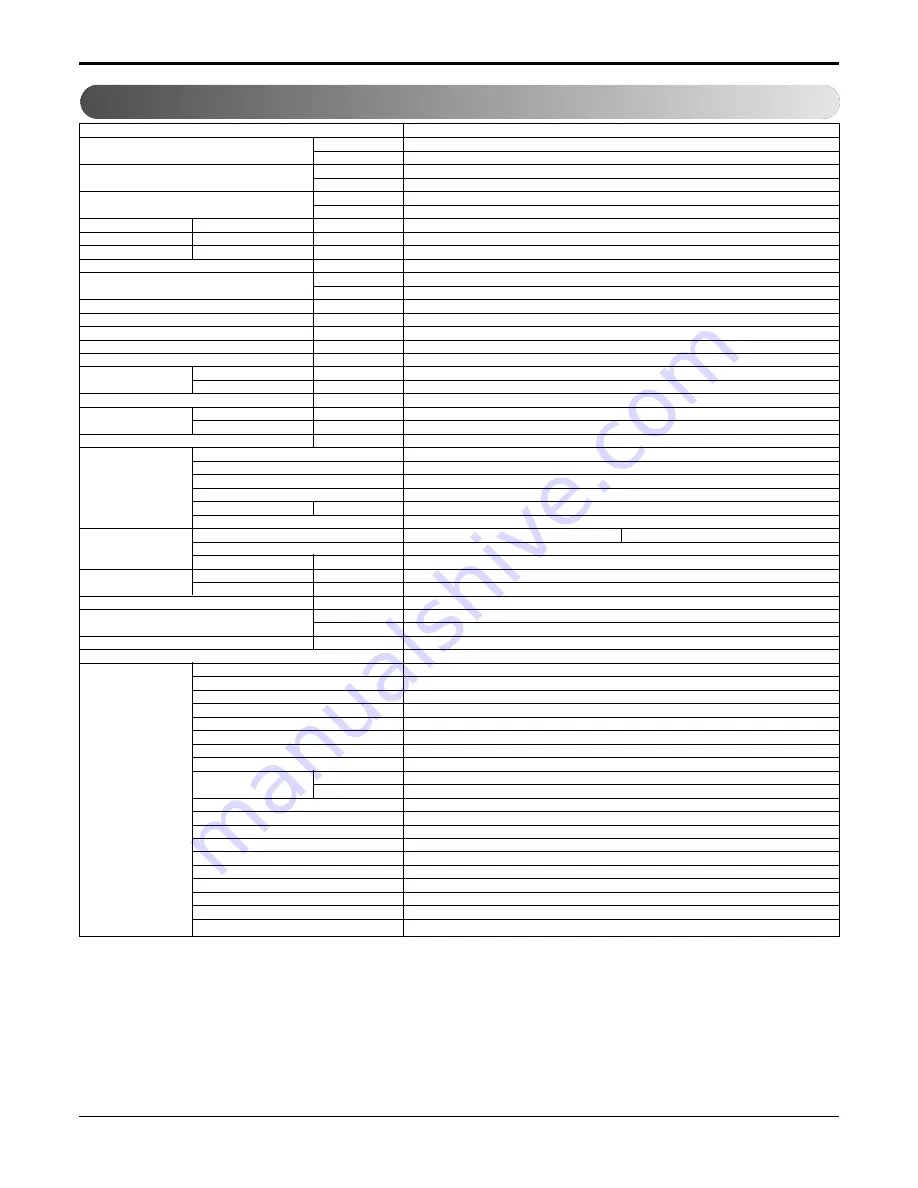
1. Specification
Models
Cooling Capacity
kW
Btu/h.
Heating Capacity
kW
Btu/h.
Electric Heater capacity kW
kW
Btu/h.
Power Input
Cooling/Heating
W
Running Current
Cooling/Heating
A
Starting current
Cooling/Heating
A
Electric Heater Current
A
EER
W/W
Btu/h.W
COP
W/W
Power Supply
Ø / V / Hz
Power Factor
%
MCA
A
MOP
A
Air Flow Rate
Indoor,Max
m
3
/min(CFM)
Outdoor,Max
m
3
/min(CFM)
Moisture Removal
l/h
Sound Level
Indoor,H/M/L
dB(A)±3
(SOUND PRESSURE,1M)
Outdoor,Max
dB(A)±3
Refrigerant & Charge
g(oz)
Compressor
Type
Model
Motor Type
Oil Type
Oil Charge
cc
O.L.P Name
Fan
Type(In/Out)
Motor Type(In/Out)
Motor Output(In/Out)
W
Heat Exchanger
Evaporator
Rows*Column*FPI
Condensor
Rows*Column*FPI
Power Supply Cable (Power Cord)
No.*mm
2
Dimensions ( W * H * D)
mm
inch
Net Weight
kg(lbs)
Tool Code(Chassis)
Features
Temperature Control
Energy Saver Mode
Prefilter(washable/anti-fungus)
Plasma Filter
Steps, Fan/Cool/Heat
Airflow Direction Control(up&down)
Airflow Direction Control(left&right)
Remote Controller Type
Setting Temperature
Cooling
Range
Heating
Auto Operation (Micom Control)
Panel Touch Type
Timer
Air Discharge
Air-Ventilation
Defrost Control
Hot Start
Look
Cabinet Type(Chassis Type)
Special Function
LP096HD3A
2.67
9,200
2.40
8,200
3.49
11,900
851
3.4/3.0
-
14
3.1
10.8
3.2
1/265/60
95.2/93.2
17.7
20
8.8(310)
20(706)
1
46/-/44
61
R410A,800(28.2)
Rotary
GKS086QAB
PSC
POE(RB68A) or PVE(FVC68D)
330
MRA12060-12026
Cross Flow Fan/Axial Fan
6/4 Poles
11/52
2Rx10Cx19FPI
3Rx17Cx20FPI
3x2.1
1,066x406x505
42x16x19-7/8
46(101.4)
YA
Thermistor
O
O
-
2/2/2
Manual
-
Wall Thermostat
54°F~86°F(12.2°C~30°C)
54°F~86°F(12.2°C~30°C)
-
Micom
12h, On/Off
Rear
O
O
-
L-Look
Slide In-Out
Electric Heater
Note:
O : Applied, - : No relation
* For circuit breaker rating, please confirm to local standards wherever necessary.
h
Some of functions are slightly different depending upon models.
h
The specification may be subject to change without prior notice for purpose of improvement.


