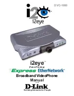
START
Check L301, L404 Voltage
(MSMP)= 2.8V ?
Re-Soldering L301, L404
No
Yes
Checking Flow : LCD
LCD display will
work properly
No
Yes
Yes
Re-soldering or Replace
VR1,VR2, R340
No
Does VR1,VR2, R340
Work Properly?
Change the Main Board
Yes
Check the
Control signal
D[0:7], LCD_RESET/,
LCD_RS/, LCD_CS/,
LWR/
Check the
CON304 Soldering
No
Re-Soldering CON304
No
Does LCD work properly?
Check voltages at each
point of Capacitor.
Change the LCD Module
Yes
1.38V 6.65V
10.4V
1.38V
1.38V
2.78V
4.07V
9.19V
0.97V
1.93V
6.71V
7.69V
8.65V
47
Z3X-BOX.COM
Summary of Contents for LG-MC2670
Page 17: ...LG MC26 70 DCN Mode Graph 2 1 2 1763 04MHz DCN384 14 Z 3 X B O X C O M ...
Page 21: ...LG MC2670 Waveform DP101 Pin 5 Graph 2 1 4 c DP101 Pin 8 Graph 2 1 4 b 18 Z 3 X B O X C O M ...
Page 32: ...LG MC2670 Circuit Diagram 29 Z 3 X B O X C O M ...
Page 55: ...LG MC2670 Appendix Z 3 X B O X C O M ...
Page 56: ...Z 3 X B O X C O M ...
Page 58: ...Z 3 X B O X C O M TX Line RX Line Local Line RD2670 ...
Page 59: ...Z 3 X B O X C O M TX Line RX Line MIC Line SPK Line RD2670 ...
Page 60: ...Z 3 X B O X C O M RD2670 ...
Page 61: ...Z 3 X B O X C O M SPK Line MIC Line RD2670 ...
Page 65: ...Description LG Part No Q ty MAIN PCB SPFY0083001 1 2 PCB Z 3 X B O X C O M ...