


6. TROUBLESHOOTING
6-1 Error Code Summary
WARNING:
When checking Resistance values, make sure to
turn off the power, and wait for the voltage to
discharge.
NOTE)
Within 3 hours after the error : Press the Ice Plus button and Freezer button simultaneously
3 hours after the error : All errors, except for "E rt", "E SS",
"E IS(except for Icing sensor)", "E gF", "E It" error, are displayed.
"E IS" which is displayed without input of user is the error of Icing Sensor.
NO
Error Detection
Category
1
Normal
None
Normal operation of Display
2
Freezer Sensor
Error
E
FS
Short or Disconnection
of Freezer Sensor
3
Refrigerator
Sensor Error
E
rS
Short or Disconnection
of Refrigerator Sensor
Check each sensor at it’s
connector.
Error Generation Factors
Remark
Error Display
4
Defrosting
Sensor Error
F
dS
Short or Disconnection
of Defrosting Sensor
5
Icing Sensor
Error
E
IS
Short or disconnection of
the sensor about Ice maker
(Icing sensor, Ice maker
sensor)
6
Pantry sensor
error
E
SS
Short or Disconnection
of Pantry Sensor
10
Poor Defrosting
F
dH
Even though it is passed
1 hour since then Defrosting,
if Defrosting sensor is not
over 46°F(8°C), it is caused
Temperature Fuse
Disconnection, Heater
disconnection, DRAIN Jam,
Poor Relay for Heater
8
Ice maker kit
defect
E
it
Other Electric system error
such as moter, gear, Hall IC,
operation circuit within I/M kit
When the ice does not drop
even when the I/M Test S/W
is pressed
9
Flow
Meter(Sensor)
Defect
E
gF
Error of flow meter or water
input or low water pressure
Error of flow meter or water
input or low water pressure or
flow meter connection
11
Abnormality of
BLDC FAN Motor
for Ice Making
E
IF
It is caused when feedback
signal isn’t over 65 seconds
during BLDC FAN motor
operating
Poor BLDC Motor connection,
DRIVE IC, and TR
12
Abnormality of
BLDC FAN Motor
for Freezer
E
FF
It is caused when feedback
signal isn’t over 65 seconds
during BLDC FAN motor
operating
Poor BLDC Motor connection,
DRIVE IC, and TR
14
Abnormality of
BLDC FAN Motor
for Mechanic
Room
E
CF
It is caused when feedback
signal isn’t over 65 seconds
during BLDC FAN motor
operating
Poor BLDC Motor connection,
DRIVE IC, and TR
15
Communication
Error
E
CO
Communication Error
between Micom of Main PCB
and Display Micom
Poor Communication
connection,Poor TR of
Transmitter and Receiver
Tx/Rx between display and
main board.
7
Room Temp
Sensor Error
E
rt
Short or Disconnectoin of
Room temp.sensor
13
Abnormality of
BLDC FAN
MOTOR For
Refrigerator
E
rF
It is caused when feedback
signal isn’t over 65 seconds
during BLDC FAN motor
operating
Poor BLDC Motor connection,
DRIVE IC, and TR
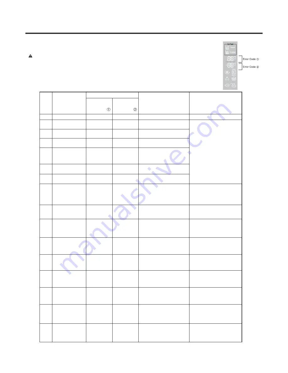
Freezer
Temperature
(Error code
)
Refrigerator
Temperature
(Error code
)
16
Humidity Sensor
Error
E
HS
Short or Disconnection of
Humidity Sensor
Poor connection of housing,
missing Humidity sensor,
sensor defect itself, short or
disconnection of harness
Summary of Contents for LFXS24623B
Page 1: ...REFRIGERATOR SERVICE MANUAL LFXS24623S LFXS24623W LFXS24623B ...
Page 20: ...5 CIRCUIT DIAGRAM ...
Page 85: ......
Page 87: ......
Page 88: ......
Page 89: ......
Page 102: ... EV 145C 145F 136D 132P 136A 131A 136B 136C 133A 133B FREEZER PARTS ...
Page 105: ... EV 625A 623B 623B 616J 616J 627D 627B 627A 619A VALVE WATER TUBE PARTS ...
Page 106: ... EV 630J 630J 600C 606A 600A 600B 630F 630A 630H 630G ICEMAKER BIN PARTS ...
Page 107: ...Aug 2014 P No MFL62526051 ...


