


- 57 -
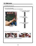
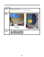
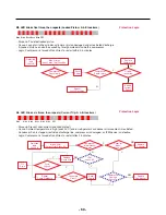
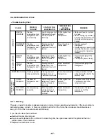
12-1 Check A
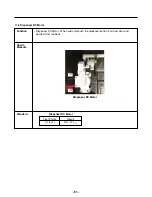
- There is PC Board located in the PCB case.
The control driver is PC board for the compressor.
- This step shows the source voltage of the driver PC board.
- Visually inspect fuse and measure DC high voltage.
- Measure the DC low voltage that supplies the inverter circuit.
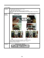
E-Inverter
A-Inverter
FC75LBNA
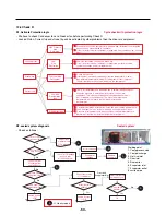
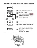
* Driver PCB located in machine room.
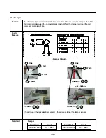
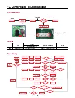
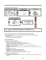
PCB Malfunction Check
Step1. Open PCB Cover
Step2. Check Driver PCB
Step 3. Check Fuse (visual inspection)
Step 4. Check DC High Voltage (Multi
Tester) Spec. about 330V DC
Step 5 Check DC low voltage (Multi Tester)
Spec. A Point 15V
B Point 5V
Step 6 Check LED Blink
See Check B
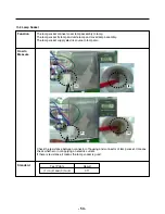
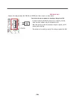
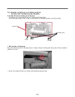
LED
B
A
GND
Voltage
Summary of Contents for LFX25978 Series
Page 19: ... 19 5 CIRCUIT DIAGRAM LFX28978 ...
Page 20: ... 20 LFX25978 ...


