background image


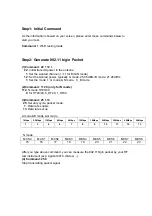
Step1: Initial Command 
 

As the information showed on your screen, please enter these commands below to 
start your test. 
 

Command: 1 

Wi-Fi testing mode 


Step2: Generate 802.11 b/g/n Packet 
 

(1)Command: 22 1 12 1 

22

: Initial transmit power in the antenna 

1

: Set the wanted channel (1~11 for B/G/N mode) 

12

: Set the wanted power, typically G mode: 25.05 dBm/ B mode: 21.26 dBm 

1

: Set the mode, 1

_

G mode & N mode , 0

B mode 


(2)

Command: 112 0 (only for N mode) 

112

: N mode HT20/40. 

0

: for HT20/40. 0

_

HT20, 1

_

HT40 


(3)Command: 25 1 13 

25

: Set duty cycle, packet mode. 

1

: Data rate enable 

13

: Data rate set up 


A mode &B mode & G mode 

1Mbps 5.5Mbps 11Mbps  6Mbps  9Mbps  12Mbps

18Mbps

24Mbps 36Mbps 48Mbps

54Mbps

1 3 4 6 7 8 9 10 

11 

12 

13 


N mode 

MCS0 MCS1 MCS2 MCS3 MCS4 MCS5 MCS6 MCS7 MCS8 

15 16 17 18 19 20 21 22 23 


After you type above command, you can measure the 802.11b/g/n packet by your RF 
test instrument (exp: Agilent 4010, IQview…). 

(4) Command: 25 0 

Stop transmitting packet signal. 


Summary of Contents for LCW-001

Page 1: ...LCW 001 Wi Fi Modem MFG Tool Command User Guide Home Appliance Company HA Control Lab Smart Task ...

Page 2: ...ave patents or patent pending applications trademarks copyrights or other intellectual property rights covering subject matter in this document The furnishing of this document does not give the recipient or reader any license to these patents trademarks copyrights or other intellectual property rights No part of this document may be communicated distributed reproduced or transmitted in any form or...

Page 3: ... mode 1_G mode N mode 0_ B mode 2 Command 112 0 only for N mode 112 N mode HT20 40 0 for HT20 40 0_HT20 1_HT40 3 Command 25 1 13 25 Set duty cycle packet mode 1 Data rate enable 13 Data rate set up A mode B mode G mode 1Mbps 5 5Mbps 11Mbps 6Mbps 9Mbps 12Mbps 18Mbps 24Mbps 36Mbps 48Mbps 54Mbps 1 3 4 6 7 8 9 10 11 12 13 N mode MCS0 MCS1 MCS2 MCS3 MCS4 MCS5 MCS6 MCS7 MCS8 15 16 17 18 19 20 21 22 23 A...

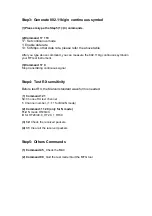
Page 4: ... your RF test instrument 3 Command 17 0 Stop transmitting continuous signal Step4 Test RX sensitivity Before test RX the Marvell standard waveform is needed 1 Command 12 1 12 Choose RX text channel 1 Channel number 1 11 for B G N mode 2 Command 112 0 only for N mode 112 N mode HT20 40 0 for HT20 40 0_HT20 1_HT40 3 32 Check the received packets 4 31 Clear all the received packets Step5 Others Comma...

Page 5: ...eiving antenna Increase the separation between the equipment and receiver Connect the equipment into an outlet on a circuit different from that to which the receiver is connected Consult the dealer or an experienced radio TV technician for help FCC Caution Any changes or modifications not expressly approved by the party responsible for compliance could void the user s authority to operate this equ...

Page 6: ...device where the antenna may be installed such that 20 cm may be maintained between the antenna and users The final end product must be labeled in a visible area with the following Contains FCC ID BEJ LGHALCW1404 The grantee s FCC ID can be used only when all FCC compliance requirements are met Manual Information To the End User The OEM integrator has to be aware not to provide information to the ...

Reviews: