-45-
3.10 SIM& Micro SD Card Interface
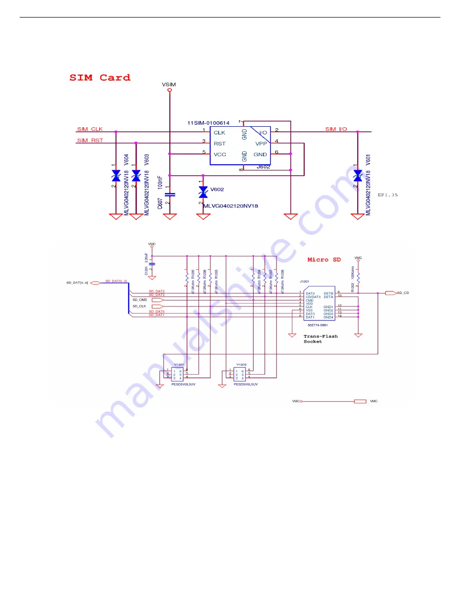
Figure.3-10-1 SIM CARD Interface
Figure.3-10-2 Micro SD CARD Interface
The MT6229 contains a dedicated smart card interface to allow the MCU access to the SIM
card. It can operate via 5 terminals, using SIMVCC, SIMSEL, SIMRST, SIMCLK and
SIMDATA.
The SIMVCC is used to control the external voltage supply to the SIM card and SIMSEL
determines the regulated smart card supply voltage. SIMRST is used as the SIM card reset
signal. SIMDATA and SIMCLK are used for data exchange purpose.
The SIM interface acts as a half duplex asynchronous communication port and its data
format is composed of ten consecutive bits: a start bit in state Low, eight information bits, and
a tenth bit used for parity checking.
Summary of Contents for KM330
Page 1: ...1 KM330 KM335 Service Manual LG Electronics ...
Page 18: ... 18 3 TECHNICAL BRIEF 3 1 Digital Main Processor Figure 3 1 1 MT6229 FUNCTIONAL BLOCK DIAGRAM ...
Page 27: ... 27 Figure 3 1 2 MT6229 BLOCK DIAGRAM ...
Page 29: ... 29 3 3 Transceiver Module MT6139 Figure 3 3 1 MT6139 FUNCTIONAL BLOCK DIAGRAM ...
Page 39: ... 39 ...
Page 41: ... 41 ...
Page 42: ... 42 3 8 Antenna Switch Module ESHS B085TB ...
Page 44: ... 44 ...
Page 46: ... 46 3 11 KEYPAD Interface ...
Page 48: ... 48 3 12 Battery Charging Block Interface Figure 3 12 1 Charging IC Interface ...
Page 52: ... 52 3 16 Camera Interface Figure 3 16 1Camera Interface ...
Page 53: ... 53 3 16 1 Pin Description ...
Page 54: ... 54 3 16 2 Major specifications ...
Page 56: ... 56 1 1 2 Circuit Diagram 32 768KHz ...
Page 58: ... 58 1 2 SIM Card Trouble 1 2 1 Test Point 1 2 2 Circuit Diagram ...
Page 60: ... 60 1 3 Vibrator Trouble 1 3 1 Test Point 1 3 2 Circuit Diagram ...
Page 63: ... 63 1 5 RTC Trouble 1 5 1 Test Point 1 5 2 Circuit Diagram ...
Page 70: ... 70 1 9 Microphone Trouble 1 9 1 Test Point TP1 1 9 2 Circuit Diagram TP1 ...
Page 72: ... 72 1 10 Receiver Trouble 1 10 1 Test Point 1 10 2 Circuit Diagram TP1 TP1 TP2 TP2 ...
Page 76: ... 76 1 12 Headphone Trouble 1 12 1 Test Point TP1 TP2 TP3 TP4 TP6 TP5 ...
Page 77: ... 77 1 12 2 Circuit Diagram TP1 TP2 TP3 TP4 TP5 TP6 TP3 TP4 TP5 TP6 ...
Page 80: ... 80 RF Trouble shooting Bluetooth MT6601 Test Point Circuit Diagram TP1 TP2 TP4 TP3 ...
Page 83: ... 83 FM receiver SI4702 Test Point Circuit Diagram TP1 TP2 TP3 TP4 ...
Page 86: ... 86 RF Transceiver MT6139 Test Point ...
Page 87: ... 87 Circuit Diagram ...
Page 88: ... 88 Checking Flow ...
Page 89: ... 89 5 DOWNLOAD 5 1 Download setup ...
Page 94: ... 94 6 BLOCK DIAGRAM ...
Page 95: ... 95 7 CIRCUIT DIAGRMA ...
Page 96: ... 96 ...
Page 97: ... 97 ...
Page 98: ... 98 ...
Page 99: ... 99 ...
Page 100: ... 100 ...
Page 101: ... 101 ...
Page 102: ... 102 ...
Page 103: ... 103 ...
Page 104: ... 104 ...
Page 105: ... 105 ...
Page 108: ... 108 8 3 BGA PIN Check of Bluetooth MT6601 MT6601 U301 BGA use BGA non use ...
Page 109: ... 109 8 4 BGA PIN Check of PMIC MT6318 MT6318 U601 BGA use BGA non use ...
Page 114: ... 114 Work Flow ...
Page 116: ... 116 11 CALIBRATION 11 1 Test Equipment set up ...
Page 120: ... 120 Press Next Start install ...
Page 121: ... 121 Press finish and install finish ...
Page 122: ... 122 Execute Measurement Automation to check equipment address Choose Devices and Interfaces ...
Page 124: ... 124 Setup your CMU Base GPIB address and power supply address ...
Page 125: ... 125 ATE Tool system setting Execute MTK _ ate demo Press Report System button ...
Page 126: ... 126 Setting your equipment Setting your power supply type Choose your Power Supply Type ...
Page 131: ... 131 How to setup your test report location Choose my computer Choose C disk ...
Page 132: ... 132 Choose program files Choose ARIMA ATE_08 08 files ...
Page 133: ... 133 Setup new file and leave the window Execute MTK _ ate demo ...
Page 134: ... 134 Press Report System button Press select test report location ...
Page 135: ... 135 Choose your setup report Press Done ...
Page 136: ... 136 Setup finish When you finish the setup then you press save change icon ...
Page 137: ... 137 Press Configuration choose Cal Setting Setting your cable loss ...
Page 138: ... 138 Press Done to save Press Configuration choose Final setting ...
Page 141: ... 141 Press Calibration Test Key in your phone bar Code ...
Page 143: ... 143 If you want see test report you can press View log file You can see the test report ...
Page 144: ... 144 If you want final test you can press initial final test ...
Page 145: ... 145 Press RF Final test ...
Page 146: ... 146 1 Handset to insert SIM card 2 Key in bar code or IMEI number 3 power on handset ...
Page 147: ... 147 ATE start final test ...
Page 148: ... 148 If ATE test finish ATE will show pass ...
Page 149: ... 149 If you want see the test report you can press View Log File ...
Page 150: ... 150 You can see the test report ...
Page 151: ... 151 If you want initial cal and final test you can press initial cal and final test ...
Page 152: ... 152 Press Cal Final ...
Page 153: ... 153 1 Handset to insert SIM card 2 Key in bar code or IMEI number 3 Power on handset ...
Page 154: ... 154 Start calibration ...
Page 155: ... 155 Calibration finish and power on handset again ...
Page 156: ... 156 Start final test ...
Page 157: ... 157 Finish Cal Final test ...
Page 158: ... 158 If you want see the report you can press View Log File ...
Page 159: ... 159 Ate show the test report ...
Page 161: ... 161 2 Install Process press Next 3 Install Process press Next 4 Install Process press Next ...
Page 162: ... 162 5 Install Process press Next 6 Install Process 7 Install Process press Finish ...
Page 163: ... 163 RF RX Check 1 Open Meta_RF_Tool 2 Pull in UART cable ...
Page 167: ... 167 5 TX Test AG8960 Need set Band Channel Power Level ...
Page 168: ... 168 13 EXPLODED VIEW REPLACEMENT PART LIST 13 1 KM330 Exploded view ...
Page 169: ... 169 Ass y exploded view ...
Page 170: ... 170 13 2 KM335 Exploded view ...
Page 171: ... 171 Ass y exploded view ...


