19
x1
EQ
VGA
BST
x1
2
47
48
16
IC201
IC101
For boost
0.5Vpp
ARF
NARF
0.5Vpp
Slicer
PLL
PWM
For fc
1.65V
RFINN
RFINP
AGCG
AGCO
81
99
98
31
30
44
45
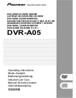
2. RF Amplifier Circuit
RF Amplifier Circuit
2-1. Input stage
The differential RF signal for data read from pick up may feed into IC401 pin 47 and pin 48.
2-2. AGC (Automatic Gain Control) Loop
This RF signal is controlled to 0.5 Vpp in VGA.
The capacitor which is connected in 44 pin is used to control constant level of amplitude.
The capacitor which is connected in 45 pin is used to control DC offset of FR signal.
2-3. Equalizer
EQ boost gain is controlled by u-com and register BST .
Fc of EQ is linear by real velocity and feed into IC101 16pin and changed by current differentially.