


- 61 -
Copyright © 2009 LG Electronics. Inc. All right reserved.
Only for training and service purposes
LGE Internal Use Only
3. Technical brief
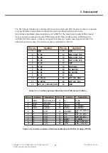
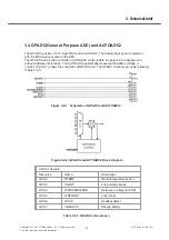
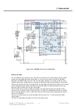
3.4 GPADC(General Purpose ADC) and AUTOADC2
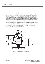
The GPADC consists of a 14 input MUX and an 8-bit ADC. The analog input signal is selected
with the MUX and converted in the ADC.
The GPADC has a built in controller, AUTOADC2, which is able to operate in the background
without software intervention. The AUTOADC2 periodically measures the battery voltage or
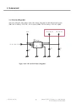
current. (Fig.3-4-1) shows the schematic of GPADC part. The GPADC channel spec is as following
(Table 3-4-1).
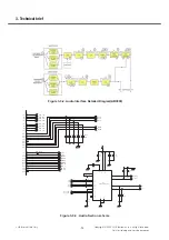
Figure 3-4-1. Schematic of GPADC and AUTOADC2
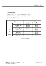
ADC 6 channels
Resource
Name
Description
GPA0
RTEMP
Radio temperature sense
GPA2
VLOOP
Loop voltage sense
GPA3
WPOWERSENSE
Reference voltage for PAM
GPA4
WRFLOOP
Lock inform
GPA6
GPA6
Headset detect
GPA7
VBACKUP
Backup battery
Table 3-4-1. GPADC channel spec
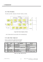
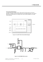
Figure 3-4-2. GPADC and AUTOADC2 Block diagram