- 16 -
ADJUSTMENT INSTRUCTIONS
[
[
. RS-232C Command
(Automatic Adjustment)
12-3. Adjustment of White Balance
O
Operate the Zero-calibration of the CA-100, then attach
sensor to PDP module surface when you adjust.
O
Manual adjustment is also possible by the following sequence.
(1) Enter ‘Ez - Adjust’ by pressing ADJ KEY on the Service
Remote Control.
(2) Select "7. WHITE PATTERN" using CH +/- Key and HEAT
RUN at least 30 minutes by pressing the ENTER Key.
(3) Receive the Window pattern signal from Digital Pattern
Generator. (AV Input: connect the ‘HDMI’)
(4) After attaching sensor to center of screen, select ‘3. White-
Balance’ of ‘Ez - Adjust’ by pressing the ADJ KEY on the
Service R/C. Then enter adjustment mode by pressing the
Right KEY (
G
) .
(5) Adjust the Hight Light using R Gain/B Gain and adjust the
Low Light using G Cut/B Cut.
(6) Adjust using /- KEY.
(R-Gain: 127 R-Cut: 63 Fix.)
High Level: 150gray
Low Level: 60gray
X; 0.285±0.003
Y; 0.285±0.003
Color temperature: 9,800°K±500°K
(7) After adjustment is complete, move to Ez - Adjust screen
by pressing the ENTER(
Y
) KEY. Then exit the adjustment
mode by press ADJ KEY.
13. Main/Sub Contrast Adjustment
Main/Sub contrast adjustment reduces the contrast difference
of Main/Sub screen in PIP/POP/SPLIT Screen.
(1) After receiving signal for at least 1 second, press the ADJ
KEY on the Service R/C and enter the ‘Ez - Adjust’ then
select ‘2. VPX3226’.
Enter adjustment mode by pressing the Right KEY(
G
).
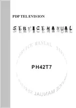
(2) When entering adjustment mode, the TV image becomes
6CH SPLIT Screen with automatic movement as in below
window.
(3) After adjusting the 1.Contrast (Main) first to see the most
clear outline of “US 6CH” letter on left Main screen,
2.Contrast (Sub) adjust to be same the contrast of right
Sub screen and contrast of left Main screen.
This time adjust using the /- Key.
(4) After adjustment is complete, exit the adjustment mode by
press ADJ KEY.
14. DVCO Adjustment
(1) After adjusting Main/Sub Contrast, receive a Digital
Pattern.
(2) Select ‘4. DVCO-Set’ by pressing the ADJ KEY on the
Service R/C and adjust by pressing the Right KEY (
G
) .
(3) When adjustment is complete, “DVCO-Set“ will appear.
Exit the adjustment mode menu by pressing ADJ key.
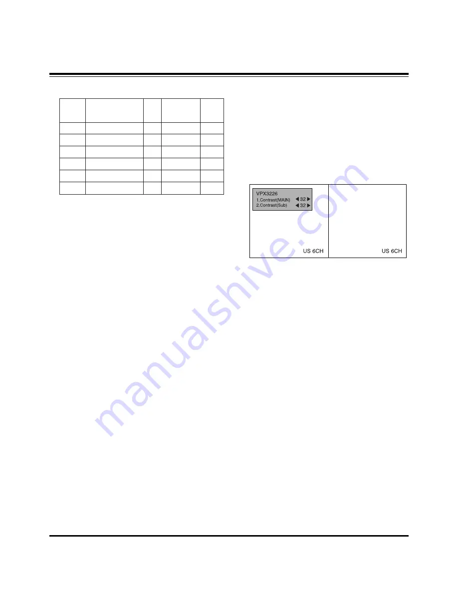
R Gain
G Gain
B Gain
R Cut
G Cut
B Cut
00
00
00
00
00
00
ff
ff
ff
7f
7f
7f
ja oo XX
jb oo XX
jc oo XX
lj oo XX
lk oo XX
ll oo XX
7f
7f(Fix.)
7f
3f(Fix.)
3f
3f
RS-232C Command
[CMD ID DATA]
MIN
CENTER
(DEFAULT)
MAX
Summary of Contents for DU-42PY10X
Page 17: ... 17 PRINTED CIRCUIT BOARD MAIN DIGITAL TOP ...
Page 18: ... 18 PRINTED CIRCUIT BOARD MAIN DIGITAL BOTTOM ...
Page 19: ... 19 PRINTED CIRCUIT BOARD TUNER ANALOG TOP ...
Page 20: ... 20 PRINTED CIRCUIT BOARD TUNER ANALOG BOTTOM ...
Page 21: ... 21 PRINTED CIRCUIT BOARD SIDE A V TOP SIDE A V BOTTOM LED TOP LED BOTTOM ...
Page 22: ... 22 PRINTED CIRCUIT BOARD POWER S W TOP KEYBOARD TOP KEYBOARD BOTTOM POWER S W BOTTOM ...
Page 23: ... 23 BLOCK DIAGRAM ...
Page 34: ......
Page 35: ......
Page 36: ......
Page 37: ......


