


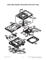

5
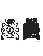
DECK MECHANISM DISASSEMBLY
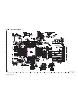
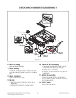
6. Belt Loading
Remove the Belt Loading.
7. Gear Pulley
Unlock the Locking Tab (L3) in direction of arrow
and then separate the Gear Pulley from the Base
Main.
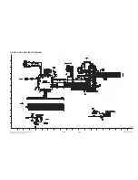
8. Gear Loading
Remove the Gear Loading.
9. Guide
1) Move the Guide in direction of arrow (A) as
Figure H-1
.
2) Separate the Guide from the Base Main.
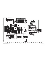
10. Deck PCB Assembly
1) Disconnect the wires (RED, BK) form the
Deck PCB Assembly by desoldering.
2) Remove the 1 screw (S3).
3) Separate the Deck PCB Assembly from the
Base Main.
11. Motor Assembly
Unlock the Locking Tab (L4) in direction of
arrow and then separate the Motor Assembly
from the Base Main.
12. FFC Cable
Remove the FFC Cable.
Gear Pulley
Belt Loading
Deck PCB
Assembly
Motor
Assembly
Base Main
Gear Loading
Guide
Base Main
Figure H-1
(L3)
(A)
(B)
(S3)
< Bottom side view >
< Bottom side view >
< Bottom side view >
< Figure H >
(L4)
BLK
RED
BRN
ORN
RED
BK
Deck PCB
Assembly
Summary of Contents for CM4550
Page 13: ...2 2 ...
Page 17: ...A60 4 SPEAKER SECTION 4 1 FRONT SPEAKER CMS4550F ...
Page 18: ...2 9 A90 4 2 SUBWOOFER SPEAKER CMS4550W ...
Page 19: ...2 10 ...
Page 50: ...4 USB 13 USB_5 V D D 14 3 31 IC501 PIN A8 IC501 PIN A7 ...
Page 51: ...3 32 ...
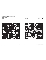
Page 66: ...3 61 3 62 2 MAIN P C BOARD TOP VIEW BOTTOM VIEW ...
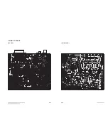
Page 67: ...3 63 3 64 3 FRONT P C BOARD TOP VIEW BOTTOM VIEW ...


