- 10 -
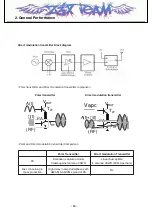
Direct modulation transmitter Block diagram
• Polar transmitter and Direct modulation transmitter comparison
• Polar and Direct modulation transmitter Comparison
T
RF
T
LF
V
BAT
PA
(RF)
A(t)
(t)
T
RF
T
LF
V
BAT
PA
(RF)
Vapc
A(t)+ (t)
Polar transmitter
Direct modulation transmitter
Polar Transmitter
Direct modulation Transmitter
PA
Nonlinear (saturated mode)
Linear Susceptible
Stable against antenna VSWR
to antenna VSWR (EVM,Spectrum)
Risk concerning in
High delay in amplitude/phase path
No
mass production
AM/AM & AM/PM spread of PA
Z3X-BOX.COM
Summary of Contents for CE500
Page 3: ... 4 Z 3 X B O X C O M ...
Page 77: ...4 TROUBLE SHOOTING 78 5 Check Tx I Q TXQP TXQN TXIN TXIP U704 Test Point Z 3 X B O X C O M ...
Page 85: ...Note 86 Z 3 X B O X C O M ...
Page 93: ... 94 8 PCB LAYOUT Z 3 X B O X C O M ...
Page 94: ... 95 8 PCB LAYOUT Z 3 X B O X C O M ...
Page 95: ... 96 Z 3 X B O X C O M ...
Page 103: ...9 CALIBRATION 104 L Standalone Test Equipment Setup Oscilloscope Z 3 X B O X C O M ...
Page 105: ... 106 Z 3 X B O X C O M ...
Page 127: ...Note 128 Z 3 X B O X C O M ...


