background image

- 7 -

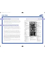
1. MAIN POWER

switches the set on or off.

Note : In some models, one power line lives even
when the main power is off.

2. MENU (option)

selects a menu.

3. OK (option)

accepts your selection or displays the current
mode.

4.

(Volume Up/Down)

adjusts the volume.
adjusts menu settings.

(Function) (option)

selects volume, Eye, picture items or brief
auto programme while the menus not display.

5.

E

(Programme Up/Down)

selects a programme or a menu item.
switches the set on from standby.
+ / - (

E

) (option)

adjusts the function or selects a programme.
switches the set on from standby.

6. POWER/STANDBY INDICATOR

illuminates brightly when the set is in standby
mode.
dims when the set is switched on.

7. REMOTE CONTROL SENSOR

8. EYE (option)

adjusts picture according to the surrounding
conditions.

9. AUDIO/VIDEO IN SOCKETS (AV3)

Connect the audio/video out sockets of exter-
nal equipment to these sockets.

S-VIDEO/AUDIO IN SOCKETS (S-AV) (option)
Connect the video out socket of an S-VIDEO
VCR to the S-VIDEO socket. 
Connect the audio out sockets of the S-VIDEO
VCR to the audio sockets as in AV3.

10. HEADPHONE SOCKET (option)

Connect the headphone plug to this socket.

11. TV/AV (option)

selects TV or AV mode.
clears the menu from the screen.
switches the set on from standby.

Front panel

Side 

panel

Side 
panel

CE/CL-25Q26 series

CE/CL-29Q26 series

CE/CL-29Q46 series

CE/CL-25/29H36 series

CE/CL-28H86 series

CE/CL-25/29H46 series

TV/AV

VOL

PR

AV3

VIDEO L/MONO  AUDIO  R

POWER

MENU

POWER

OK

VOL

PR

STAND-BY

VIDEO 

AV3

(L/MONO) AUDIO (R)

1

6

7

114

10

5

9

1

6 7 2 3 4

5

9

POWER

MENU

O K

VOL

VOL

PR

STAND BY

1

2 4 5 3

8

6 7

8

S-VIDEO

VIDEO 

L/MONO

R

AUDIO 

AV3

S-VIDEO

VIDEO 

L/MONO

R

AUDIO 

AV3

S-VIDEO

VIDEO

(L/MONO)

AUDIO

AV3

R

L

10

10

9

9

9

10

POWER

MENU

OK

VOL

PR

7

MENU

O K

VOL

PR

STAND BY

POWER

2 3

6

8

4 5

1

MENU OK

VOL

PR

POWER

7

2 3

6

8

4 5

1

1

6

8

7 23 4 5

Summary of Contents for CE-28H86T

Page 1: ...TION BEFORE SERVICING THE CHASSIS READ THE SAFETY PRECAUTIONS IN THIS MANUAL CHASSIS MC 007A MODEL CE CL 28H86T website http biz LGservice com e mail http www LGEservice com techsup html Apr 2001 Printed in Korea P NO 3828VD0077H ...

Page 2: ...NTS Contents 2 Safety Precautions 3 Specifications 4 Control Descriptions 5 Disassembly Instructions 8 Adjustment Instructions 9 Exploded View 14 Exploded View Parts List 15 Replacement Parts List 16 SVC Sheet ...

Page 3: ...perform an AC leakage current check on the exposed metallic parts of the cabinet such as antennas terminals etc to be sure the set is safe to operate without damage of electrical shock Leakage Current Cold Check Antenna Cold Check With the instrument AC plug removed from AC source connect an electrical jumper across the two AC plug prongs Place the AC switch in the on positioin connect one lead of...

Page 4: ...art 1 Full A V in out Scart 2 Half Audio out A V in out O External In Output Audio In 0 5Vrms 3db over 10Kohm Audio Out 0 5Vrms 3db below 1Kohm Video In Out 1Vp p 3db 75ohm R G B In 0 7Vp p 3db O Feature Auto programme Manual programme SVM Scanning Velocity Modulation Digital Eye Digital Comb Filter Auto Sleep Dynamic Focus Programme Editing PSM Picture Status Memory CTI Double Window Teletext TOP...

Page 5: ...o cassette recorder 6 SSM Sound Status Memory recalls your preferred sound setting 7 PSM Picture Status Memory recalls your preferred picture setting 8 EYE option switches the eye function on or off 9 TELETEXT BUTTONS option These buttons are used for teletext For further details see the Teletext section 10 MUTE switches the sound on or off 11 ARC Aspect Ratio Control changes the picture format 12...

Page 6: ... in clockwise direction 9 4 PIP switches on or off the 9 or 4 sub pictures 17 SLEEP sets the sleep timer 18 SWAP or Q VIEW returns to the previously viewed programme COLOURED BUTTONS These buttons are used for teletext only TELETEXT models or programme edit Battery installation The remote control handset is powered by two AAA or AA type bat teries To load the batteries turn the remote control hand...

Page 7: ...e audio video out sockets of exter nal equipment to these sockets S VIDEO AUDIO IN SOCKETS S AV option Connect the video out socket of an S VIDEO VCR to the S VIDEO socket Connect the audio out sockets of the S VIDEO VCR to the audio sockets as in AV3 10 HEADPHONE SOCKET option Connect the headphone plug to this socket 11 TV AV option selects TV or AV mode clears the menu from the screen switches ...

Page 8: ...d Amp Board 2 Remove respective 6 screws for speaker on the front cabinet Fig 2 2 CPT Removal 1 Pull out the CPT board from the CPT neck 2 Place the front cabinet on soft material not to mar the front surface or damage control knobs 3 Remove 4 screws securing the picture tube mounting brackets to the front cabinet 4 Carefully separate CPT from the front cabinet PICTURE TUBE HANDLING CAUTION Due to...

Page 9: ...be 2 4 0 05Vdc O RF AGC Automatic Gain Control Adjustment 1 Input PAL B G 05 CH 2 Connect Multimeter to TP2 J15 AGC adjustment point 3 Adjust VR121 until the voltage of Multimeter becomes 2 5 0 1V O Screen Voltage Adjustment 1 Tune the RF Modulator to receive a PAL or SECAM signal 2 Press MIX button on remote controller for Service to get into the Screen Adjust Mode 3 Adhere the Color Analyzer on ...

Page 10: ...that a digital circle pattern looks like exact circle EP East west Parabolar Adjust so that middle portion of the outermost left and right vertical line looks like parallel with vertical lines of the CPT EC East west Coner Adjust so that the vertical line at every 4 corners of the screen looks like parallel with the vertical lines of the CPT ET East west Trapezium Adjust to make the length of top ...

Page 11: ...H 0 1FFH 0 1FFH 0 01FF 0 01FF 00C8 0190 0065 000B 0007 0008 0005 0003 0001 00F0 0158 Range 29 Flat 29 S Flat Menu FP NP SP S1 VOL S2 VOL 0 127 0 127 0 127 0 127 0 127 0011 0045 001E 0042 0042 Range DATA Mode CONTRAST BRIGHT COLOR SHARPNESS 90 50 50 50 100 55 60 60 60 60 40 40 50 60 40 30 STANDARD DYNAMIC MILD GAME Menu CR CG CB RG GG BG 0 511 0 511 0 511 0 511 0 511 0 511 50 50 50 370 370 370 Rang...

Page 12: ...V MONO VOL H PH DGS TILT 200PRO AV2 HOTEL KEY SYS M VOL OSD T LAN 1 GAME TEXT TOP China Australia EYE Turbo Search SCART STEREO I II MONO Middle East Africa India VOL H Phone Degaussing TILT China Only Back JACK 2EA HOTEL 0 X X X Australia Only X X X X X X Normal VOL X X Back JACK 1EA X Option 1 Option 2 Option 3 Option 4 Menu ...

Page 13: ... 13 MEMO ...

Page 14: ... 14 P801 540 530 520 943 400 913 150 510 112 170 104 120 330 320 321 300 550 310 EXPLODED VIEW ...

Page 15: ...ART NO DESCRIPTION D850 ICV01 ICN01 IC01 IC02 ICV02 ICN02 IC03 ICN03 IC04 ICN05 IC101 IC102 IC301 IC302 IC601 IC801 IC803 IC851 IC853 IC855 IC856 IC901 Q07 Q08 D01 D02 D03 D04 D101 D124 D301 D302 D401 D402 D403 D404 D405 D406 D407 D408 D412 D601 D602 D802 D803 D804 D851 D852 0ISK100300A 0IIT312000A 0IIT341000J 0ICTMIH001B 0ICTMIH002A 0IAL241610B 0IFA754207A 0ISG282200A 0IFA752700A 0IKE780500Q 0ISG...

Page 16: ...C105 C106 C108 C109 C110 C111 C112 C113 C114 C115 C121 C122 C123 C124 C125 C126 C127 C128 C129 C130 C131 C132 C134 C135 C136 C137 C138 C139 C140 C141 C142 C145 C147 C148 C149 C183 C201 C202 C203 C204 C205 C206 C207 C208 C209 C221 C222 C223 C224 0CN1030F679 0CE227DD618 0CX3300K409 0CX3300K409 0CE106DF618 0CE335DK618 0CE475DK618 0CN1040K949 0CE227DF618 0CN1020K519 0CE476DD618 0CN1030F679 0CN1030F679...

Page 17: ...03 C804 C806 C807 C808 C809 C811 C813 C814 C815 C817 C851 C852 C853 C854 C855 C856 C857 C858 C859 C860 C861 C862 C863 C864 C866 C867 C870 C871 C872 C873 C901 C902 C903 C904 C905 C906 C907 C908 C909 C910 C911 C912 C913 CN05 CN07 CN10 0CQ1041N509 0CE477DJ618 0CN1040K949 0CE477DK618 0CE477DH618 0CQZVBK002D 181 091G 181 001F 181 011C 181 091G 0CE107BJ618 0CK1020K515 181 120K 0CK10201515 0CQZVBK002A 18...

Page 18: ...2012 16V 10 R TP X7R 220000PF 2012 16V 10 R TP X7R 22UF STD 16V M FL TP5 390P 50V K LOCA NO PART NO DESCRIPTION FB01 FB201 FB202 FB222 FB241 FB401 FB801 FB802 FB803 FB852 FB853 FB902 FB903 J29 J51 J89 J122 JV26 JV27 L01 L02 L101 L102 L103 L104 L122 L123 L126 L201 L202 L203 L204 L221 L222 L223 L224 L241 L242 L245 L246 L401 L402 L851 L853 L901 LN01 LN03 LN05 125 022K 125 022K 125 123A 125 123A 125 1...

Page 19: ...9 R60 R61 R62 R63 R64 R65 R66 R67 R69 R70 R71 R101 R102 R103 R104 R105 R106 R107 R108 R125 R128 R130 R132 R133 R135 R136 0RD4701F609 0RD4701F609 0RD4701F609 0RD1000F609 0RD1000F609 0RD1001F609 0RD1001F609 0RD1001F609 0RD4302F609 0RD5101F609 0RD1000F609 0RD2701F609 0RD4701F609 0RD3300F609 0RD1301F609 0RD8201F609 0RD1000F609 0RD5601F609 0RD1000F609 0RD1000F609 0RD1000F609 0RD1000F609 0RD5600F609 0RD...

Page 20: ...00 TA52 430 OHM 1 2 W 5 00 TA52 470 OHM 1 2 W 5 00 TA52 100 OHM 1 6 W 5 00 TA52 27K OHM 1 6 W 5 00 TA52 1 6K OHM 1 6 W 5 00 TA52 62K OHM 1 6 W 1 00 TA52 1K OHM 1 6 W 1 00 TA52 5 6 OHM 1 W 5 00 TA62 LOCA NO PART NO DESCRIPTION 0RD1501F609 0RD3301F609 0RD4700F609 0RS2701H609 0RS1501H609 0RS1501H609 0RD0392F609 0RD1000F609 0RD1001F609 0RD1801H609 0RD0332H609 0RS1001K607 0RS0221K607 0RS1801H609 0RMZVB...

Page 21: ...O PART NO DESCRIPTION SG901 SG902 SG903 SG904 SW01 SW02 SW03 SW04 SW801 T101 T102 T103 T104 T105 T801 X01 XN01 XV01 Z101 Z102 Z103 A1 A1 A2 A2 A2 A2 F853 JK201 JK202 JK203 PA02 RL801 RL802 SK901 TH801 TU101 VD801 165 004A 165 004A 165 004A 165 004A 140 315A 140 315A 140 315A 140 315A 6600VM2002A 166 C06D 166 C06D 166 C06D 166 C04C 166 C06D 150 F06T 156 A01L 156 A02R 6202VDB007B 6200VQS001Q 6200VQS...

Page 22: ... 330 5020V00227B BUTTON POWER 5020V00227C BUTTON POWER SILVER 400 3809V00099D BACK COVER ASSY MA LOCAL 510 6871VSM728B PWB ASSY CPT 28 PHILPS STV5109 SE 520 6871VMM635G PWB ASSY MAIN 007A CE 6871VMM635W PWB ASSY MAIN 007A CL 530 6871VSM819A PWB ASSY 007A VCD W O PIP SVHS S 540 6871VSM589A PWB ASSY STRO MC007A RF ST W H_PHONE 550 6871VSM842A PWB ASSY CURRENT HARMONICS STANDARD 913 332 229B SCREW DR...

Page 23: ...Video Audio C P No 3854VA0071A S1 2000 06 15 ...

Page 24: ...P01 C2 P101 A5 P181 A3 P601 A2 P602 A1 P02A F1 P03A C1 P04A C1 P05A B1 P06A B1 P401A F4 P401B F4 P401C F4 P401D F4 P402A F5 P403A E5 P404A F5 P502A A3 P503A B3 P504A C3 P603A D5 P604A D5 P605A A2 P606A A3 P801A G1 P801B G1 P802A E1 P802B E1 PA02 F1 Q02 B3 Q03 C3 Q04 C3 Q05 D1 Q06 E1 Q07 B1 Q08 A1 Q101 B5 Q102 B5 Q103 A5 Q121 B5 Q122 C4 Q123 C4 Q124 C5 Q125 A4 Q126 B4 Q127 A4 Q201 B5 Q221 D5 Q301 D...

Page 25: ...P or VCD BOARD 5V REG IC854 5 9V REG IC852 3 3 3V REG IC04 13V 9V 5V TUNER 33V SOUND Vcc B 28 S VIDEO SEL BLOCK DIAGRAM TROUBLESHOOTING GUIDE C804 F P 801 SW P 801 T1111 T801 R802 DB801 pin4 T802 R809 D802 18V ICP V 01 ICP V 01 Q401 Q402 T401 OPTION 33V F854 D861 R405 D850 L853 T402 3V pin 32 of IC01 3 3V 0V IC01 FR403 FR413 D405 D406 IC301 ICP V 01 IC852 3 IC854 5 FR406 D408 D858 Q856 Q05 IC851 I...

Page 26: ...SVC SHEET 3854V A0071A S1 SVC SHEET 3854V A0071A S2 ...

Reviews: