


4-6
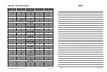
PIN NO.
SYMBOL
TYPE
DESCRIPTION
R2
FEGIO10
3.3V LVTTL I/O,
5V-tolerance,
2, 4, 6, 8 mA PDR,
75K pull-down (3.3 V)
PC RS232 serial receive data.
The pin is spike-free at power-on stage.
Alternate function :
1. High speed serial output port. (CLOCK)
2. Internal monitored signal output
3. LED Control Output. Initial “0” Output
4. Line-in input master clock
5. Serial interface control line
6. Slave I2C clock
7. General IO
R3
FEGIO11
3.3V LVTTL I/O,
5V-tolerance,
2, 4, 6, 8mA PDR,
75K pull-down (3.3 V)
PC RS232 serial transmit data.
The pin is spike-free at power-on stage.
Alternate function :
1. High speed serial output port. (Data)
2. Internal monitored signal output
3. Line-in input bit clock
4. Serial interface control line
5. Slave I2C clock
6. General IO
N4
FEGIO3
3.3V LVTTL I/O,
5V-tolerance,
2, 4, 6, 8mA PDR,
75K pull-down (0 V)
LED Control Output. Initial 0 Output.
The pin is spike-free at power-on stage.
Alternate function :
1. Internal monitored signal output
2. General IO
P1
FEGIO4
Analog Output
Read gain switch 4
Alternate function :
1. LCD serial interface command enable.
2. LCD_DRV: Sqare wave output for LCD control.
3. Internal monitored signal output
4. Line-in input left-right clock
5. General IO.
J1
FEGIO5
Analog Output
Read gain switch 6
Alternate function :
1. SIDM
2. LCD serial interface command enable.
3. Internal monitored signal output
4. Line-in input data
5. General IO.
K7
FEGIO6
Analog Output
Read gain switch 6.
The pin is not allowed to pull-up in circuit layout
Alternate function :
1. SIDM
2. LCD serial interface command enable.
3. Internal monitored signal output
4. General IO.
K5
FEGIO7
3.3V LVTTL I/O,
5V-tolerance,
2, 4, 6, 8 mA PDR,
75K pull-down (0 V)
General IO.
The pin is spike-free at power-on stage.
The pin is not allowed to pull-up in circuit layout.
K6
FEGIO9
3.3V LVTTL I/O,
5V-tolerance,
2, 4, 6, 8 mA PDR,
75K pull-down (0 V)
General IO.
The pin is spike-free at power-on stage.
Alternate function :
1. Internal monitored signal output
2. Spoke input
3. Power on reset input, high active.
4. General IO.
D5
HAVC
Analog Output
Decoupling Pin for Reference Voltage of Main and Sub Beams
A1
INA
Analog Input
Input of Main Beam Signal (A)
B2
INB
Analog Input
Input of Main Beam Signal (B)
B1
INC
Analog Input
Input of Main Beam Signal (C)
Summary of Contents for BPM35
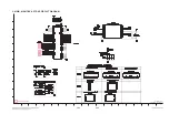
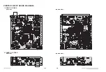
Page 59: ...3 46 WAVEFORMS OF MAJOR CHECK POINT 1 SYSTEM PART 1 IC501 X TAL 27 MHz 1 1 ...
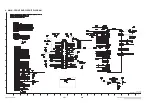
Page 60: ...3 47 2 SYSTEM PART 2 SYSTEM MEMORY IC601 BA0 IC601 WE IC601 CAS IC601 CK 2 3 5 4 2 3 4 5 ...
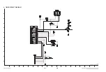
Page 61: ...3 48 3 HDMI PART H_SDA H_SCL HDMI_CLK_N HDMI_0_N 9 8 7 6 6 7 8 9 ...
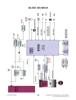
Page 63: ...3 50 BLOCK DIAGRAM ...
Page 83: ...4 12 ...