3-13
DIGITAL DISPLAY & MEDIA TRAINING MASTER
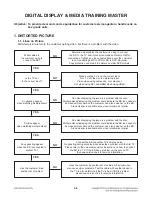
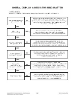
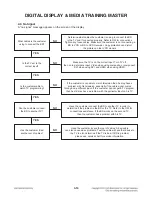
What cables is the customer
using to connect the BD?
NO
YES
Determine what cables the customer is using to connect the BD to
the TV and if connected properly. Refer to OM for connections.
Tighten any loose cables. Make sure the customer is not connecting a
BD to VCR. Copy protection can distort the picture on older VCR models.
Is the TV set to the
correct input?
NO
YES
Make sure the TV is on the correct input according to the
connections in use. Video when using composite, or component.
DVI when using DVI, and HDMI when using HDMI.
Is color fine
when watching multiple discs?
NO
YES
One disc displaying the issue is a problem with the disc.
Make sure the discs the customer is using are compatible with the BD
by checking “playable discs” in the owners manual. Multiple discs
displaying the problem indicates a problem with the BD player.
Is color fine
when watching a TV program?
NO
YES
If the cable or satellite programming is connected through another
input and the customer does not get color, the customer has a problem
with his television. If a TV program does have the color, the problem
may be the BD player, the cables being used, or the TV itself.
Is color fine when the BD is
connected to another TV?
NO
YES
Connect the BD to another TV and play a disc.
Good color during disc play back indicates a problem with the first TV.
Please refer to the owners manual for instructions on how to connect
the BD to a TV. If the BD has a problem on the second TV,
then see service chart for service information.
Has the customer tried
another set of cables?
NO
Have the customer try another set of cables. A bad cable
can also cause video problems. Test the cable with another device to
the TV to also determine if the TV is bad. If the BD is the problem,
please see service chart for service information.
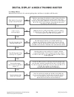
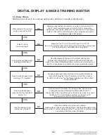
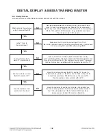
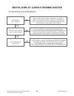
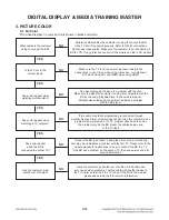
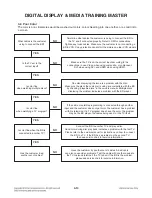
3-2. Poor Color
The color is poor. Examples would be washed out colors, colors bleeding into one another, or a solid tint to
a screen.
Summary of Contents for BPM35
Page 59: ...3 46 WAVEFORMS OF MAJOR CHECK POINT 1 SYSTEM PART 1 IC501 X TAL 27 MHz 1 1 ...
Page 60: ...3 47 2 SYSTEM PART 2 SYSTEM MEMORY IC601 BA0 IC601 WE IC601 CAS IC601 CK 2 3 5 4 2 3 4 5 ...
Page 61: ...3 48 3 HDMI PART H_SDA H_SCL HDMI_CLK_N HDMI_0_N 9 8 7 6 6 7 8 9 ...
Page 63: ...3 50 BLOCK DIAGRAM ...
Page 83: ...4 12 ...

