background image

31

4. Spindle Circuit

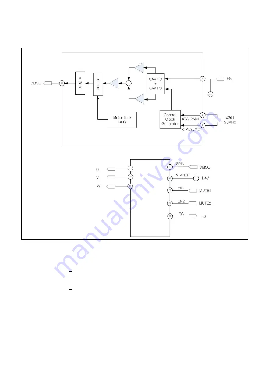
4-1-1. Block Diagram(FGCAV Servo)

4-1-2. FG CAV  Servo 

1) CD 48x CAV : CD-ROM, CD-R
2) CD 40x CAV : CD-RW
3) DVD 13x CAV : DVD+RW
4) DVD 12x CAV : DVD-ROM DL
5) DVD 16x CAV : DVD-ROM
6) DVD 16x CAV : DVD+R

When drive read PRESS CD, Closed Session CD-R/RW, the spindle motor is controlled using FG CAV Spindle
Servo. FG signal(TPIC2016G4 19pin) input to SFG in DSP ICMT1959 44pin).
The spindle controller in DSP IC uses SFG as spindle rotation frequency feedback, therefore the FG CAV
Spindle Servo doesn't work well if FG generation is abnormal.

The spindle controller PWM output signal SPD(MT1959 34pin) input to SPIN in Drive IC(TPIC2016G4 1pin) 
after Low-Pass Filtering. 
The PWM output signal U, V, W signal(TPIC2016G4 12, 13, 14pin) drives Spindle Motor without using a sensor,
and FG pulse output is generated as 18 pulses/rotation. 

IC101

MT1959H

IC601

TPIC2016G

Summary of Contents for BP50NB40

Page 1: ...Slim Blu ray Disc Rewriter SERVICE MANUAL MODEL BP50NB40 BUP1 P NO MFL67140078 April 2015 Printed in Korea ...

Page 2: ...gional Code 21 INTERNAL STRUCTURE OF THE PICK UP 22 25 1 Block Diagram of the Pick up 22 2 Pick up Pin Assignment 23 3 Signal detection of the P U 24 DESCRIPTION OF CIRCUIT 26 32 1 ALPC Circuit 26 2 Focus Circuit 27 3 Tracking Sled Circuit 29 4 Spindle Circuit 30 MAJOR IC INTERNAL BLOCK DIAGRAM AND PIN DESCRIPTION 33 48 TROUBLESHOOTING GUIDE 49 48 GLOSSARY 53 BLOCK DIAGRAM 54 CIRCUIT DIAGRAM 55 57...

Page 3: ...can read as much as 25 Gbytes of digital data stored in a BD ROM R RE disc It can write as much as 50 Gbytes of digital data into BD R DL RE DL disc and can read as much as 50 Gbytes of digital data stored in a BD ROM DL R DL RE DL disc This Blu ray Disc Rewriter Drive can easily meet the upcoming MPC level 3 specification and its Enhanced Intelligent Device Electronics E IDE and ATAPI interface a...

Page 4: ...and writes DVD R RW RAM with CPRM 9 Supports to read CD layer of Super Audio CD Hybrid type 10 Supports to read AVCHD format DVD disc 11 Supports to read and write AVCREC format DVD disc 12 Supports to read DVD layer of Hybrid Blu ray disc 1 3 Performance outline 1 Write speed BD R SL 2x CLV 4x PCAV 6x CAV SL M DISC 2x CLV 4x PCAV DL 2x CLV 4x PCAV 6x CAV TL 2x CLV 4x PCAV QL 2x CLV 4x PCAV SL LTH...

Page 5: ...o CSS Compliant Disc 8x CAV SL DL CD R RW ROM 24x 24x 24x CAV CD DA 24x CAV 3 Sustained Transfer Max rate BD 26 97 MB s 6x DVD 11 08 MB s 8x CD 3 6 MB s 24x 4 Legacy data Transfer mode USB High Speed 480Mbps 60MB s USB Full Speed 12Mbps 1 5MB s 5 Multimedia MPC 3 compliant 1 3 Performance outline Definition Transfer Rate SPEED MEDIA Transfer rate UNIT 1x BD 4 495 MB s 220 bytes s 2x BD XL 8 99 MB ...

Page 6: ... Ver 1 3 BD R TL QL 100 GB 128 GB Ver 2 0 BD RE SL DL 25 GB 50 GB Ver 2 1 BD RE TL 100 GB Ver 3 0 DVD DVD ROM SL DL 4 7 GB 8 5 GB Ver 1 1 DVD R 4 7 GB Ver 2 0 for Authoring read only 4 7 GB Ver 2 1 for General read write DVD R DL 8 5 GB Ver 3 0 DVD RW 4 7 GB Ver 1 2 Rev 1 0 2 0 3 0 DVD RAM 4 7GB side Ver 2 2 DVD R 4 7 GB Ver 1 3 DVD R DL 8 5 GB Ver 1 2 DVD RW 4 7 GB Vol 1 Ver 1 3 Vol 2 Ver 1 0 CD ...

Page 7: ... RW Disc at Once DAO Incremental Recording Restricted Overwrite 6 DVD R SL DL Sequential Recording 7 DVD RW Random Write 8 DVD RAM Random Write 9 CD R RW Disc at Once DAO Session at Once SAO Track at Once TAO and Packet Writing 2 3 Disc diameter 120mm 80mm 2 4 Data capacity User Data Block BD R RE ROM 2048 bytes block DVD R RW RAM ROM R RW 2048 bytes block CD Yellow Book 2048 bytes block Mode1 Mod...

Page 8: ... 2x 2x CLV 2 77 R SL 4x 2x CLV 3 3 4x PCAV 2 77 4 57 5 54 R SL 8x 16x 2x CLV 3 3 8x CAV 2 77 4 57 11 08 DVD R SL 4x 2 4x CLV 3 3 4x PCAV 3 32 4 57 5 54 R SL 8x 16x 2 4x CLV 3 3 8x CAV 3 32 4 57 11 08 DVD R DL 4x 2x CLV 2 4x ZCLV 2 77 2 77 5 54 R DL 8x 2x CLV 2 4 6x ZCLV 2 77 2 77 5 54 8 31 DVD R DL 2 4x 2 4x CLV 3 32 R DL 8x 2 4x CLV 2 4 4 6x ZCLV 3 32 3 32 5 54 8 31 DVD RW 2x 2x CLV 2 77 RW 4x 2x...

Page 9: ...DVD R DL 3 3 8x CAV 4 57 11 08 DVD R DL 8cm 3 3 5x CAV 4 57 6 92 DVD RW 3 3 8x CAV 4 57 11 08 DVD RAM 2x CLV 2 77 3x CLV 4 15 3 5x PCAV 4 15 6 92 DVD RAM 8cm 2x CLV 2 77 CD R ROM 10 24x CAV 1 5 3 6 CD RW 10 24x CAV 1 5 3 6 CD 8cm 6 8 10 5x CAV 1 0 1 65 3 3 2 Video and Audio Playback Note Read Speed basically finalized discs specification BDMV SL 2x CLV 8 99 BDMV DL 2x CLV 8 99 DVD ROM Video SL 4x ...

Page 10: ...RW ROM 10 12 Mode 1 10 9 Mode 2 Condition It is assumed that the worst case raw error rate of the disc is 10 3 3 6 Spin up time without Multi session Spin up time Time to drive ready mode from standby mode BD ROM SL 15 s typ Time to drive ready mode from power on 4 s typ Time to drive ready mode from sleep DVD ROM SL 13 s typ Time to drive ready mode from power on 4 s typ Time to drive ready mode ...

Page 11: ...0 Non Condensing 4 5 Dew point temperature restrictions Less than 29 ºC 4 6 Altitude Operating 0 m to 3000 m Non operating 0 m to 12000 m 4 7 Vibration 1 Non Operating 19 6 m s2 2 0 G No physical and electrical damage No disc loaded 10 to 500 Hz sine wave random 1oct min at Each of 3 directions1 1 3direction X left and right Y back and front Z top and bottom axis 2 Transportation 8 04 m s2 0 82 G ...

Page 12: ...st Conditions C 150pF R 330 ohms 20 times discharge 7 POWER REQUIREMENTS 7 1 Source voltage 5V 5 Ripple Less than 100 mVp p 7 2 Current Stand By 1 110 mA typ Continuous Read 850 mA typ CD ROM 24x max CAV 900 mA typ DVD ROM 8x max CAV 950 mA typ BD ROM 6x max CAV Continuous Write 900 mA typ CD R 24x max CAV 900 mA typ DVD R 8x max CAV 1000 mA typ DVD R DL 6x max CAV 950 mA typ BD R 6x max CAV Seek ...

Page 13: ...efer to Section 13 10 Mass Max 270g 11 Mechanicals 11 1 Disc Loading Drawer type manual load Electrical release 11 2 Mounting Requirements 13 Horizontal 15 15 15 15 Note Operation with postures other than the above drawings is not guaranteed ...

Page 14: ... Emergency Eject Hole The emergency eject procedure should only be used to retrieve your disc if the drive fails to eject Caution Shut down the power supply when this eject will be used 1 Bezel 2 Eject Button 4 Power Loading Busy Indicator 12 2 Rear View USB 2 0 ...

Page 15: ...15 12 3 Connector Pin Assignment Pin Assignment Pin No Function Type 1 VBUS Power 2 D Signal 3 D Signal 4 GND GND 5 GND Shield GND USB 2 0 ...

Page 16: ...1 Top Cover A Remove the 4 Foots at bottom B Release 2 Screws at bottom C And then remove the Top cover D After Release 4 Screws and lift the slim tray DISASSEMBLY 16 ...

Page 17: ...17 A B C 1 2 3 4 5 A00 A01 002 003 461 005 001 463 006 462 004 PBM01 B B EXPLODED VIEW ...

Page 18: ...el Assembly external BUP1 004 MAZ63904201 Bracket PRESS SECC 0 5 external BUP1 SECC 0 5t 005 MAZ63904301 Bracket PRESS SUS301 0 3 extrnal BUP1 SUS 006 MDP61887005 Foot COMPLEX BOTTOM foot for RP15 15 1 PBM00 EBR77419401 PCB Assembly Main BUP1 Main PCB Assy PBM01 EBR77429201 PCB Assembly HZ BUP1 BCUP1 B B main PCB assy SCREW 461 FAB30112507 Screw Taptite N SPECIAL S 4 5M 2 8M SWCH18A BLACK SEOUL ME...

Page 19: ...CSS RF data slice EFM demodulator CiRC error correction Buffer Memory controller CSS controller Atapi interface control Data PLL Servo ADC Focus tracking control output Sled control output CAV Spindle control P up Unit HOP B7710G CD DVD BD IC301 MT1959 TE CSO GEN FE GEN DRAM U COM SRAM Flash ROM IC101 MT1959H P up Unit JPA27Z ...

Page 20: ...VD Disc for the scrambled of data 1 DVD ROM and DVD player of host generate the KEY 1 respectively transfer to opposite part the KEY 2 is received recognizes the data transfer or not with this value and generates the bus key encoded the data 2 Encoded Disc Key and Title Key host is transfer with the bus Key 3 DVD player of host reads the key value and uses the value to restore the scrambled data R...

Page 21: ...UM PLW PNG NZL AUS 4 The disc has the regional code of 8 bit Example The disc manufactured in the U S A has the number one Transfer to MPEG 2 board reading the regional code Receiving data from the MPEG 2 board and output through the monitor If the board is setting to the regional code 1 for the U S A Check the received regional code to number 1 all or not transfer the data to VGA card in accordan...

Page 22: ...WEB LDD WEN LDD LDD WEN0B LDD WEN1 LDD WEN1B LDD IAPC LDD GND LDD Vcc LDD F02 ACT F02 ACT Tr ACT Tr ACT F01 ACT F01 ACT Vcc FSPD GND FSPD ENB FSPD DATA AFSPD CLK FSPD OUTP FSPD OUTN FSPD SB STPM SA STPM SA STPM SB STPM A4 2W A2 2W RFP 2W RFN 2W A1 2W A3 2W SW2 2W Vcc 2W Vref 2W GND 2W B4C4 2W B2C2 2W SL 2W GND BD Vref BD Vcc BD GS1 BD SW1 2W B1 BD B1C1 2W B6 BD B3C3 2W A3 BD A4 BD A2 BD A1 BD GS2 ...

Page 23: ...23 2 CONNECTOR 66 PIN ASSIGNMENT ...

Page 24: ...24 ...

Page 25: ...signal is generated in DSP IC IC101 MT1959H controls the pick up s left and right shift to find to track on Disc 3 RF Signal A B C D This signal is converted to DATA signal in DSP IC IC101 MT1959H 25 Pick Up module Photo Diode Tracking Focusing Infrared Iaser k EF1 EF4 EF2 EF3 A D B C A D B C k EF1 EF4 EF2 EF3 Offset TE Tp Sub2 Main Tp 2 Sub1 Track Center E4 E3 E1 E2 D C A B F4 F3 F1 F2 EF1 E1 F1 ...

Page 26: ... variation RDAC is for Read Power control and W1DAC is for Write Power control VDAC is for the reference voltage of FM Ipac Vref FM FM are analog singal and SEN SDIO SCLK are digital signal 26 Filter RDAC VDAC W1DAC LPF LPF S H S H LDD 103 Iapc 37 5 Vref 40 108 FM 23 107 FM 24 35 SEN 29 33 SDIO 30 34 SCLK 31 IC101 MT1959H CN801 Optical Pick up FM DESCRIPTION OF CIRCUIT 1 ALPC Automatic Laser Power...

Page 27: ...cus Error Signal FE generates from focus error detection block in DSP IC MT1959 using Conventional Astigmatism Detection method Differential Astigmatism Detection method Focus Gain and path can be changed at the DSP IC according to the disc The Focus Search operation is using FE PE Signal therefore check FE PE signals when Focusing is failed The role of DSP IC MT1959 is Focus Digital Controller Th...

Page 28: ...led Compensator ADC TE Offset Calibration Signal Calculation VAR_INA VAR_IND VAR_INE VAR_INH IC101 MT1959H MPPO SVO_MPPO_OFFSET SVO_SPPO_OFFSET Generation Generation SFEO Generation TE 39 FMSO 42 FMSO2 91 TACT 31 TACT SL2N SL1N SL2P SL1P 30 A 8 B TOIN TRO MUTE1 MUTE2 FMSO FMSO2 1 4V EN1 EN2 SL2IN 10 A 6 B 9 39 30 21 3 SL1IN 2 V14REF 42 IC601 TPIC2016G4 ...

Page 29: ...29 3 1 2 Block Diagram Seek IC101 MT1959H ...

Page 30: ...ersion Digital Equalizer Block and D A Conversion in MT1959H the output signal TRD MT1959H 30pin is input to Drive IC 39pin The drive output signal TACT TACT generated according TOIN TPIC2016G4 39pin and drives tracking actuator in the P U unit 3 2 2 Sled Servo The working distance of tracking actuator is too short to cover whole disc radius Sled Servo make P U move by little and little so that th...

Page 31: ...IC2016G4 19pin input to SFG in DSP ICMT1959 44pin The spindle controller in DSP IC uses SFG as spindle rotation frequency feedback therefore the FG CAV Spindle Servo doesn t work well if FG generation is abnormal The spindle controller PWM output signal SPD MT1959 34pin input to SPIN in Drive IC TPIC2016G4 1pin after Low Pass Filtering The PWM output signal U V W signal TPIC2016G4 12 13 14pin driv...

Page 32: ...D RW 2 4x 4x 6x CLV 8x ZCLV When drive write DVD RAM R RW R RW CD R CD RW the spindle motor is controlled using Wobble CLV Spindle Servo The DSP Controller in MT1959H uses WOBSIG as linear velocity feed back therefore the Wobble CLV Spindle Servo doesn t work well when WOBSIG signal is abnormal The spindle controller PWM output signal SPD MT1959H 34pin input to SPIN in Drive IC TPIC2016G4 1pin aft...

Page 33: ...MAJOR IC INTERNAL BLOCK DIAGRAM AND PIN DESCRIPTION IC101 MT T1959H 1 1 Block Diagram 33 MT1959H ...

Page 34: ...1 2 Pin Layout RF Part 34 ...

Page 35: ...35 ...

Page 36: ...36 ...

Page 37: ...37 ENDEC Part ...

Page 38: ...38 ...

Page 39: ...39 ...

Page 40: ...40 ...

Page 41: ...41 ...

Page 42: ...42 ...

Page 43: ...43 ...

Page 44: ...44 ...

Page 45: ...45 IC601 TPIC2016G SPINDLE MOTOR AND 10CH ACTUATOR DRIVER Terminal Assignments ...

Page 46: ...t monitor 25 FB1PX IN Feed back input terminal for 1PX converter 26 P5V_SW PS Power supply terminal for DCDC converters 27 REG1PX OUT REG1PX DCDC converter switching output GPOUT1 28 PGND_SW PS GND terminal for DCDC converters 29 REG3P3 OUT REG3P3 DCDC converter switching output terminal GPOUT2 30 FB3P3 IN Feed Back input terminal for 3 3V DCDC converter 31 CSWO OUT Power switch output for 5V OEIC...

Page 47: ...47 55 SLED2 OUT Sled2 negative output terminal 56 P5V_2 PS Power supply terminal for SLED channel drivers IN input OUT output PS power MISC miscellaneous ...

Page 48: ... REG3P3 3 3V 10u V1PXSEL GND A5V 10u P5V_SW P5V 10u 1 xV DC DC V1PX DC DC V3P3 Digital core pre driver power FET SLED END detection STEP END detection CSW LED DAC PWM DAC PWM DAC PWM DAC PWM DAC PWM DAC PWM DAC PWM P5V P5V int 3 3V Regulator A5V ENDDET_ENA ENDDET_ENA ENDDET_SLCT SLD_ENA TLT_ENA FCS_ENA TRK_ENA STP_ENA SPM_ENA SPM_LSMODE CSW_ON LED_ON Power monitor SIOV 200k SIOV 33k 10V P5Vx2 A5V ...

Page 49: ...able of CN201 Tray operating is abnormal Connect the Power cable correctly Replace the Front PCB NO YES YES 49 Check the connection of Power cable of CN651 Check the pick up FFC Replace the pick up NO Tray open does not work The Eject button does not work ...

Page 50: ... Connect the ATAPI and Power cable correctly NO Check the connection of ATAPI and Power cable of CN201 Check the model name between Firmware and Drive Replace the main PCB Correspond the model name between Firmware and Drive NO YES YES ...

Page 51: ...e connection of FFC and CN651 CN602 CN601 Recognition fail case1 Connect each cables are correctly Replace the main PCB NO Replace the pick up NO YES YES YES After close the tray check the Pick up operate normally ...

Page 52: ...c use new BD R disc Go to Writing Part Check YES NO Remove the Dust Fingerprint and if the disc has long width Scratch change it Does the disc have any Dust Scratch Fingerprint NO YES Use LG bundle Software Write Tool Version Is the write Tool version supported by LG Super Multi Blue Drive YES NO NO Check disc information on Writng Tool If you get some data information with Non Recordable Disc Mes...

Page 53: ...f changed conditions of disc and change in operating temperature Jitter The 16 value of the time variation between leading and trailing edges of a specific I3 I11 pit or land as measured by Time Interval Analysis Deviation The difference between a fixed value of Pit length and Land length TOC Table Of Contents in the Lead in Area the subcode Q channel contains information about the Tracks on the d...

Page 54: ...M E F A l a t i g i D A T A S n i p 8 0 1 B M 2 M O R h s a l F M O C c n E s u B S C A A M A R D B M 4 r o t a r e n e G S W f s n a r T S D V L r e B C P n i a M X Z 7 2 J U t r a P D M T V F 7 9 9 9 D B m h o R r e t r e v n o c C D C D I H V c i n o s a n a P Z 7 2 A P J V 5 p 8 T N C d r a o B e g d i r B z H M 0 3 V 5 0 2 B S U B S U V 5 r e w o P h s a l F l a i r e S K 2 1 5 Y H P 0 2 B S ...

Page 55: ...5 DVDD33O85 86 GIO4 87 GIO36 LED5 88 GIO5 89 GIO6 90 GIO7 MUTE3 91 VREF 92 MVDD2592 93 MVDD2593 94 MVDD2594 95 DVDD33O95 96 DVDD12I96 97 MPXOUT1 98 MPXOUT2 99 MPXOUT3 100 AVDD12100 101 RSTI 102 VDAC0 103 VRDCO 104 VWDC1O 105 VWDC2O 106 VWDC3O 107 FPDOCD 108 D V D O D P F IINR RSTI FM IIN3 FM C135 0 1UF D401 1SS400GTE61 1608 R124 10K 1 C131 0 1UF R122 1K C132 2 2UF V 5 2 M R125 10K 1 C134 0 1UF 1 A...

Reviews: