background image

- 3 -

SAFETY PRECAUTIONS

Many electrical and mechanical parts in this chassis have special safety-related characteristics. These parts are identified by      in
the Schematic Diagram and Replacement Parts List. 
It is essential that these special safety parts should be replaced with the same components as recommended in this manual to
prevent X-RADIATION, Shock, Fire, or other Hazards. 
Do not modify the original design without permission of manufacturer.

General Guidance

An 

isolation Transformer should always be used

during

the servicing of a receiver whose chassis is not isolated from
the AC power line. Use a transformer of adequate power rating
as this protects the technician from accidents resulting in
personal injury from electrical shocks.

It will also protect the receiver and it's components from being
damaged by accidental shorts of the circuitry that may be
inadvertently introduced during the service operation.

If any fuse (or Fusible Resistor) in this TV receiver is blown,
replace it with the specified.

When replacing a high wattage resistor (Oxide Metal Film
Resistor, over 1W), keep the resistor 10mm away from PCB.

Keep wires away from high voltage or high temperature parts.

Due to high vacuum and large surface area of picture tube,
extreme care should be used in 

handling the Picture Tube

.

Do not lift the Picture tube by it's Neck.

X-RAY Radiation

Warning: 

To determine the presence of high voltage, use an accurate
high impedance HV meter.

Adjust brightness, color, contrast controls to minimum. 
Measure the high voltage. 
The meter reading should indicate 
23.5 

±

1.5KV: 14-19 inch, 26 

±

1.5KV: 19-21 inch,

29.0 

±

1.5KV: 25-29 inch, 30.0 

±

1.5KV: 32 inch

If the meter indication is out of tolerance, immediate service
and correction is required to prevent the possibility of
premature component failure.

Before returning the receiver to the customer, 

always perform an 

AC leakage current check

on the exposed

metallic parts of the cabinet, such as antennas, terminals, etc.,
to be sure the set is safe to operate without damage of
electrical shock. 

Leakage Current Cold Check(Antenna Cold Check)

With the instrument AC plug removed from AC source,
connect an electrical jumper across the two AC plug prongs.
Place the AC switch in the on position, connect one lead of
ohm-meter to the AC plug prongs tied together and touch other
ohm-meter lead in turn to each exposed metallic parts such as
antenna terminals, phone jacks, etc. 
If the exposed metallic part has a return path to the chassis, the
measured resistance should be between 1MΩ and 5.2MΩ. 
When the exposed metal has no return path to the chassis the
reading must be infinite.
An other abnormality exists that must be corrected before the
receiver is returned to the customer.

Leakage Current Hot Check 

(See below Figure) 

Plug the AC cord directly into the AC outlet.

Do not use a line Isolation Transformer during this check. 

Connect 1.5K/10watt resistor in parallel with a 0.15uF capacitor
between a known good earth ground (Water Pipe, Conduit, etc.)
and the exposed metallic parts.
Measure the AC voltage across the resistor using AC
voltmeter with 1000 ohms/volt or more sensitivity.
Reverse plug the AC cord into the AC outlet and repeat AC
voltage measurements for each exposed metallic part. Any
voltage measured must not exceed 0.75 volt RMS which is
corresponds to 0.5mA.
In case any measurement is out of the limits specified, there is
possibility of shock hazard and the set must be checked and
repaired before it is returned to the customer.

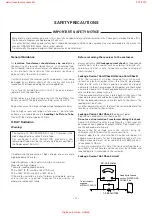
Leakage Current Hot Check circuit

The source of X-RAY RADIATION in this TV receiver is the
High Voltage Section and the Picture Tube.
For continued X-RAY RADIATION protection, the
replacement tube must be the same type tube as specified in
the Replacement Parts List.

1.5 Kohm/10W

To Instrument’s
exposed 
METALLIC PARTS

Good Earth Ground
such as WATER PIPE,
CONDUIT etc.

AC Volt-meter

IMPORTANT SAFETY NOTICE

0.15uF

www.freeservicemanuals.info

27/1/2015

Digitized in Heiloo, Holland

Summary of Contents for BN315

Page 1: ...CE MANUAL CAUTION BEFORE SERVICING THE CHASSIS READ THE SAFETY PRECAUTIONS IN THIS MANUAL CHASSIS RE 058B MODEL BN315 MODEL BN315 JD website http biz LGservice com e mail http www LGEservice com techsup html www freeservicemanuals info 27 1 2015 Digitized in Heiloo Holland ...

Page 2: ...TIONS 4 REPLACING OF LAMP 9 SPECIFICATIONS 11 ADJUSTMENT INSTRUCTION 13 PRINTED CIRCUIT BOARD 18 BLOCK DIAGRAM 21 EXPLODED VIEW 22 EXPLODED VIEW PARTS LIST 23 REPLACEMENT PARTS LIST 24 SVC SHEET www freeservicemanuals info 27 1 2015 Digitized in Heiloo Holland ...

Page 3: ...ck on the exposed metallic parts of the cabinet such as antennas terminals etc to be sure the set is safe to operate without damage of electrical shock Leakage Current Cold Check Antenna Cold Check With the instrument AC plug removed from AC source connect an electrical jumper across the two AC plug prongs Place the AC switch in the on position connect one lead of ohm meter to the AC plug prongs t...

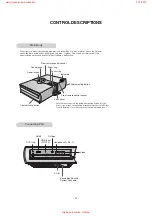
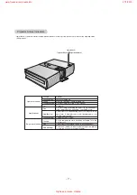
Page 4: ...ht points red blue or green This can be a normal result of the manufacturing process and does not always indicate a malfunction Focus ring Zoom ring Lens cover Push the lens cover into the inside after pulling it open into the front If you mount on the ceiling after pushing the cover the lens cover is installed If not the cover may overlap projecting lens HDMI S Video SVC Only RGB Input PC DTV Com...

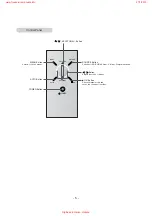
Page 5: ...Button MENU Button Selects or closes menus AUTO Button Button Adjusts functions of menus SOURCE Button Switches to RGB HDMI Video S Video Compoment mode A OK Button Checks present mode and saves the change of functions www freeservicemanuals info 27 1 2015 Digitized in Heiloo Holland ...

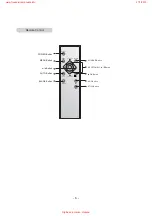
Page 6: ... AUTO BLANK ARC STILL OK KEYSTONE KEYSTONE POWER Button SOURCE Button KEYSTONE D EButton A OK Button ARC Button STILL Button AUTO Button BLANK Button F GButton MENU Button www freeservicemanuals info 27 1 2015 Digitized in Heiloo Holland ...

Page 7: ...mp is starting up Unit is in operation Lamp is turned on Projector lamp is cooling 1 min 30 sec Power off Projector lamp is reaching the end of its life and needs to be replaced with a new lamp over 2000 hours The projector is experiencing an error Retry Power On again later If lamp indicator is red flashing again con tact the service center The lamp cover is open A high temperature state has been...

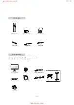
Page 8: ... ceiling installer for projector Contact your service personnel for replacing of lamp Remote Control Power Cord Video Cable Owner s Manual Computer Cable SCART to RCAjack option Lamp Portable Bag S Video Cable Projection Screen 1 5V 1 5V 2 Batteries size AAA Ceiling installer for projector HDMI Cable Component Cable www freeservicemanuals info 27 1 2015 Digitized in Heiloo Holland ...

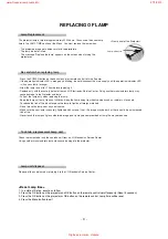
Page 9: ...mp away from heat sources such as radiators stoves etc To reduce the risk of fire do not expose the lamp to liquids or foreign materials Do not place the lamp near any heat source Make sure the new lamp is securely tightened with screws If not the image may be dark or there could be an increased risk of fire Never touch the lamp unit glass otherwise image quality may be compromised or lamp life ma...

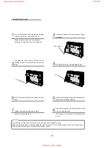
Page 10: ...rt the new lamp gently into the correct position Make sure it is inserted correctly 7 Tighten the screws you removed in step 3 Make sure they are fixed firmly 8 Close the lamp cover and install the screws from step 2 to install the cover If the lamp cover is not installed correctly the unit will not power on Replacing the Lamp Bolt Knob Using another manufacturers lamp may cause damage to the proj...

Page 11: ...n Method 1 Performance Follow the Standard of LG TV test 2 RCA JACK performance Follow the standard of LG 3 Standards of extra requirement SAFETY CB EN55013 Electric wave CE EN55020 A General Specification 11 No Item Video input applicable system Power Input Voltage Market Screen size Aspect ratio Operating Temperature Operating Humidity Storage Temperature Storage Humidity 1 NTSC M 2 NTSC 4 43 3 ...

Page 12: ...480i 576i 1 Menu Source Auto OK D E G keystone F keystone Power Normal Film Sports Contrast Brightness Color Tint Sharpness Cool Normal Warm Full 16 10 16 9 4 3 Zoom1 Zoom2 no Korean English Deutsch Italiano Espanol Chinese French Swedish Portuguese LGE Code DVI D D Sub 15 pin Y Pb Pr Phone Jack Y Phone Jack S VIDEO jack Earphone jack only for download 1 2 3 4 5 6 7 8 9 10 11 12 13 14 Specificatio...

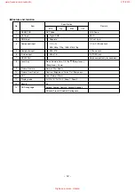
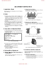
Page 13: ...it the service menu 5 Preparation for Adjustment 1 Power is connected in set to be power on 2 Do heat run 5minutes 4 Folding Mirror Adjustment 4 1 Before adjusting check the position of Folding MIrror Check the position of Folding Mirror in the base of up down left right surface Fig 2 1 Check the Lower Position As shown Fig 2 fix lower position of mirror so they are vertically aligned with the bas...

Page 14: ...justment to the right and mark where the image is aligned 2 Turn screw C up down adjustment to the left and mark where the image is aligned 3 Turn screw C up down adjustment to the right left and mark where the image is aligned Fix the adjustment screw in position 4 Final Adjustment Fix the adjustment screw in position 1 2 3 adjustment twice and find the optimum position Check the image with the n...

Page 15: ...on 3 Don t clean the DMD with the high pressure The static electricity and pressure will damage the DMD TI reference DMD Handing Specification DMD Cleaning 15 Up down screw A Right tighten direction Adjustment part Screen state Initial state State after adjusting Screw direction Description At first upside illuminator goes down and right illuminator also goes down in detail Left loosen direction A...

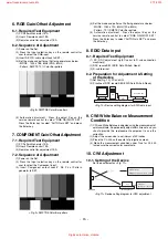
Page 16: ...djustment Press the adjust Key on the service remote control to select RGB GAIN OFF SET Press the Enter key to select AUTO Gain SET and press the Enter key 8 EDID Data input 8 1 Required Test Equipment 1 PC DDC adjustment Jig PC serial to D sub connection machinery 2 DDC record S W EDID Data Write Read 3 D sub terminal 8 2 Preparation for Adjustment Setting of the device 1 Set like Fig 10 PC and J...

Page 17: ... 270 and average value is 268 4 Check the red pattern whether it is entirely uniform If it is uniform press ENTER button to exit after pressing EXIT button FULL RED disappear 11 White Balance Adjustment 11 1 Required Test Equipment 1 Illuminometer Model CL 200 1EA Chromaticity measurement from projection screen center 2 Pattern Generator DVI input 3 Set fixing device 1EA 4 Remote control 1EA 11 2 ...

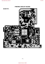
Page 18: ... 18 PRINTED CIRCUIT BOARD MAIN TOP www freeservicemanuals info 27 1 2015 Digitized in Heiloo Holland ...

Page 19: ... 19 MAIN BOTTOM www freeservicemanuals info 27 1 2015 Digitized in Heiloo Holland ...

Page 20: ... 20 CONTROL DMD TOP DMD BOTTOM SENSOR TEMP SENSOR www freeservicemanuals info 27 1 2015 Digitized in Heiloo Holland ...

Page 21: ... 21 RGB BLOCK DIAGRAM www freeservicemanuals info 27 1 2015 Digitized in Heiloo Holland ...

Page 22: ...42 43 75 55 56 60 59 61 63 65 64 66 62 9 10 12 8 6 5 4 3 7 1 2 14 11 13 26 33 71 27 34 35 36 37 38 39 40 70 53 67 68 28 25 29 30 32 31 69 83 81 64 64 57 58 72 80 82 73 74 85 84 76 78 77 EXPLODED VIEW www freeservicemanuals info 27 1 2015 Digitized in Heiloo Holland ...

Page 23: ...MA 42 4810V01044B Bracket PRESS SECC T0 8 DUCT LAMP FAN No Part No Descriptions 43 4972V00125B Supporter COMPLEX POLYURETHAN FANMOUNT 44 4810V01049A Bracket MOLD LUPOY DUCT PC ABS BLOW DIR 45 3550V00472B Cover COMPLEX LAMP RD JT91 SECC EGI PRESS 46 3550V00505A Cover MOLD PC FRONT RD JT91 PC GF35 BK 47 3580V00107C Door BN315 BOTTOM LENS COVER SILVER 48 4810V01040A Bracket MOLD LUPOY COVER RD JT91 P...

Page 24: ...80OHM 200MW LOCA NO PART NO DESCRIPTION IC100 IC101 IC102 IC104 IC105 IC106 IC107 IC109 IC110 IC200 IC201 IC202 IC203 IC204 IC205 IC3 IC300 IC301 IC301 IC302 IC303 IC303 IC304 IC305 IC40 IC401 IC403 IC407 IC408 IC409 IC410 IC450 IC500 IC518 IC557 IC610 IC611 IC651 IC652 IC653 IC654 IC801 IC802 IC904 IC950 IC951 IC952 IC953 IC954 IC954 IC955 IC955 0IMCRSG007A 0IMMRAL034C 0IMI623200B 0IKE702700D 0IK...

Page 25: ...211 C212 C213 C214 C215 C216 C217 C218 C219 C220 C221 C222 C223 C224 C225 C226 C227 C228 C229 C230 C231 C232 C233 C234 C236 C237 C238 C239 C240 C241 C256 C257 C258 C265 C266 C267 C268 C301 C302 C303 C304 C305 C306 C306 C307 C308 C309 C309 C310 C311 C312 C313 0CK104CF56A 0CK104CF56A 0CK104CF56A 0CK104CF56A 0CK104CF56A 0CK104CF56A 0CK104CF56A 0CK104CF56A 0CK104CF56A 0CK104CF56A 0CK104CF56A 0CK104CF5...

Page 26: ... C369 C370 C371 C372 C373 C373 C374 C375 C376 C377 C378 C379 C381 C382 C383 C384 C385 C386 C390 C391 C40 C403 C404 C405 C406 C407 C408 C410 C411 C412 C413 C414 C417 C419 C421 C422 C424 C425 C426 C427 C428 C429 C430 C431 C432 C433 C434 C435 C436 C437 C438 C439 C440 C441 0CK104CF56A 0CK104CF56A 0CK104CF56A 0CK104CF56A 0CC100CK41A 0CK104CF56A 0CK104CF56A 0CK104CF56A 0CK104CF56A 0CK104CF56A 0CK104CF56...

Page 27: ...C549 C550 C551 C552 C553 C554 C555 C556 C557 C558 C559 C560 C561 C562 C563 C564 C565 C566 C567 C568 C569 C570 C571 C572 C573 C574 C575 C576 C577 C578 C579 C580 C581 C582 C583 C584 C585 C586 C587 C588 C589 C590 C591 C592 C593 C594 C595 C596 C597 C598 C599 C600 C601 0CK104CF56A 0CK104CF56A 0CK104CF56A 0CK104CF56A 0CK104CF56A 0CK104CF56A 0CK104CF56A 0CK104CF56A 0CK104CF56A 0CK104CF56A 0CK104CF56A 0CK...

Page 28: ...1 C701 C702 C703 C704 C705 C706 C708 C708 C709 C710 C711 C712 C713 C715 C716 C717 C718 C719 C720 C721 C722 C731 C732 C734 C735 C736 C737 C738 C739 C740 C751 C752 C755 C756 C757 C758 C759 C760 C761 C762 C763 C764 C765 C766 C767 C768 C800 C801 C802 C809 C810 C811 0CC101CK41A 0CK103CK51A 0CK104CF56A 0CK104CF56A 0CK335FK66A 0CK104CF56A 0CK104CF56A 0CK104CF56A 0CK335FK66A 0CZZTCT006C 0CK104CF56A 0CK104...

Page 29: ... 50V X7R LOCA NO PART NO DESCRIPTION C967 C968 C969 C970 C971 C972 C973 C974 C975 C976 C978 C979 C980 C981 C982 C983 C984 C985 C986 C987 C989 C1 C2 C3 C4 C5 IC1 JK200 P10 P103 P401 P517 P557 P651 P651B P652 P731 P801 P951 P952 P953 P954 P955 P956 P957 P957B P958 P959 P965B AR416 0CK104CK56A 0CE476WF6DC 0CE476WF6DC 0CK104CF56A 0CE106WFKDC 0CK104CF56A 0CK104CF56A 0CK104CF56A 0CK104CF56A 0CK104CF56A ...

Page 30: ...R13 R130 R131 R132 R133 R134 R135 R136 R138 R139 R14 R140 R141 R142 R145 R146 R149 R15 R150 R151 R153 R154 R155 R156 R157 R158 R159 R16 R160 R161 R162 R163 R169 R170 R171 R200 R201 R202 R203 R204 R205 R205 R206 R206 R207 R207 R208 R209 R209 R210 R211 R211 0RJ1002D677 0RJ1002D677 0RJ0102D677 0RJ1002D677 0RJ1002D677 0RJ4701D677 0RJ1002D677 0RJ0102D677 0RJ4701D677 0RJ4701D677 0RJ0222D677 0RJ1002D677 ...

Page 31: ...ON R306 R307 R308 R309 R310 R311 R312 R313 R314 R315 R315 R316 R317 R318 R318 R319 R319 R320 R320 R322 R324 R325 R325 R326 R326 R327 R327 R328 R329 R330 R330 R331 R332 R332 R333 R333 R334 R335 R336 R337 R338 R339 R340 R341 R342 R343 R344 R345 R346 R347 R348 R350 R351 R352 0RJ1002D677 0RJ0822D677 0RJ6801D677 0RJ1002D677 0RJ0822D677 0RJ0822D677 0RJ0822D677 0RJ0752D677 0RJ0752D677 0RJ0752D677 0RJ3000...

Page 32: ...ION R466 R467 R468 R469 R471 R481 R485 R486 R500 R501 R502 R503 R504 R506 R507 R512 R515 R517 R518 R518 R519 R520 R521 R522 R523 R524 R525 R526 R527 R528 R529 R530 R531 R533 R536 R539 R541 R542 R543 R544 R545 R548 R549 R550 R551 R552 R553 R554 R555 R556 R557 R558 R561 R562 0RJ0472D677 0RJ0472D677 0RJ0472D677 0RJ0472D677 0RJ1000D677 0RJ0472D677 0RJ0102D677 0RJ0000D677 0RJ1002D677 0RJ1002D677 0RJ000...

Page 33: ...ON R634 R635 R636 R637 R638 R639 R640 R641 R642 R643 R651 R652 R653 R654 R657 R658 R659 R660 R661 R662 R663 R664 R665 R666 R667 R668 R669 R670 R671 R673 R674 R675 R676 R677 R678 R679 R680 R681 R702 R703 R704 R705 R706 R707 R708 R709 R710 R711 R712 R713 R714 R715 R716 R717 0RJ0392D477 0RJ0392D477 0RJ0392D477 0RJ0392D477 0RJ0392D477 0RJ0392D477 0RJ0000D677 0RJ0000D677 0RJ0000D677 0RJ0000D677 0RJ1002...

Page 34: ...10W 1608 R TP LOCA NO PART NO DESCRIPTION R959 R960 R961 R962 R962 R963 R963 R964 R965 R966 R967 R968 R969 R970 R971 R972 R973 R974 R975 R976 R977 R978 R979 R980 R981 R982 R983 R984 R985 R986 R987 R988 R989 R990 R991 R992 R993 R994 R994 R995 R996 R997 R998 R999 D10 D100 D103 D403 D557 D653 D815 D816 0RJ1000D677 0RJ0222D677 0RJ1002D677 0RJ0222D677 0RJ4701D677 0RJ1002D677 0RJ1002D677 0RJ1002D677 0RJ...

Page 35: ...X0 9MM MLB 201209 0120P N2 120OHM 2X1 2X0 9MM MLB 201209 0120P N2 120OHM 2X1 2X0 9MM MLB 201209 0120P N2 120OHM 2X1 2X0 9MM MLB 201209 0120P N2 120OHM 2X1 2X0 9MM MLB 201209 0120P N2 120OHM 2X1 2X0 9MM LOCA NO PART NO DESCRIPTION L652 L653 L654 L655 L656 L731 L732 L801 L802 L806 L951 R244 R245 R246 R321 R322 R323 X101 X200 X301 J502 JK201 JK302 JK503 CA1 IC103 IC501 IC956 IC957 L1 L2 M1 NR03 W1 X5...

Page 36: ...www freeservicemanuals info 27 1 2015 Digitized in Heiloo Holland ...

Page 37: ...www freeservicemanuals info 27 1 2015 Digitized in Heiloo Holland ...

Page 38: ...www freeservicemanuals info 27 1 2015 Digitized in Heiloo Holland ...

Page 39: ...www freeservicemanuals info 27 1 2015 Digitized in Heiloo Holland ...

Page 40: ...Jun 2006 Printed in Korea P NO 3828VD0236H www freeservicemanuals info 27 1 2015 Digitized in Heiloo Holland ...
Reviews: