


13
TOP VIEW
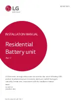
17. Plate the Wall Mounting Bracket Top
Support in right plate as shown in
fi gure and fi x on Battery Control Unit
using three (3) M6 Flange Bolts
* Tighten the M6 Flange Bolts with a
torque of 5Nm.
Plac
e the spac
er
In the line HERE
Plac
e the spa
cer
In the line HERE
Plac
e the spac
er
In the line HERE
Plac
e the spa
cer
In the line HERE
Plac
e the spac
er
In the line HERE
e the spa
cer
n the line HERE
Plac
e the spac
er
In the line HERE
Plac
e th
esp
acer
In the line HERE
Plac
e th
e sp
acer
In the line HERE
Pla
ce t
he
spa
cer
In the line HERE
Pla
ce t
he
spa
cer
In the line HERE
18. Re-attach the top cover.
* Tighten the M5xL65 Flange Bolt
(4ea) with a torque of 5N·m.
Plac
e th
e sp
acer
In the line HERE
Plac
e th
e sp
acer
In the line HERE
Plac
e th
e sp
acer
In the line HERE
Plac
e th
e sp
acer
In the line HERE
Pla
ce t
he
spa
cer
In the line HERE
Pla
ce t
he
spa
cer
In the line HERE
Pla
ce t
he
spa
cer
In the line HERE
Pla
ce t
he
spa
cer
In the line HERE
Plac
e th
e sp
acer
In the line HERE
Plac
e th
e sp
acer
In the line HERE
Pla
ce t
he
spa
cer
In the line HERE
Pla
ce t
he
spa
cer
In the line HERE
Handle
Front Cover
19. Open the front cover.
* Hold the handle and turn it
counterclockwise.
M5 PH Bolt 6ea
Front Protection Cover
20. Loosen 6 bolts and remove the Front
Protection Cover.
* Be careful not to drop the bolts into
the pack at this stage.
Connector for
Ethernet cable
Hole #2
Hole #1
21. Assemble the adapter or cap
according to regional regulations.
Insert the RMD ethernet cable
through Hole #2 and connect the
cable. Then proceed to Section 3.2
Installation for Remote Monitoring
Device (RMD).
Internal cable
Hole #2 Communication cable
Hole #1 Power cable
22. Assemble the adapter or cap
according to regional regulations.
Then insert the power and
communication cables through the
holes from outside of the pack.
* Arrange the internal cable as
required to avoid blocking the holes
for external cables.
23. Connect the cables according to their
application.
* Refer to Section 3.3 Cable
Connections.
24. Arrange the power cables and
communication cables separately
using cable ties.
Summary of Contents for BLGRESU10HP
Page 19: ......