SINGLE ZONE ART COOL GALLERY WALL
MOUNTED INSTALLATION MANUAL
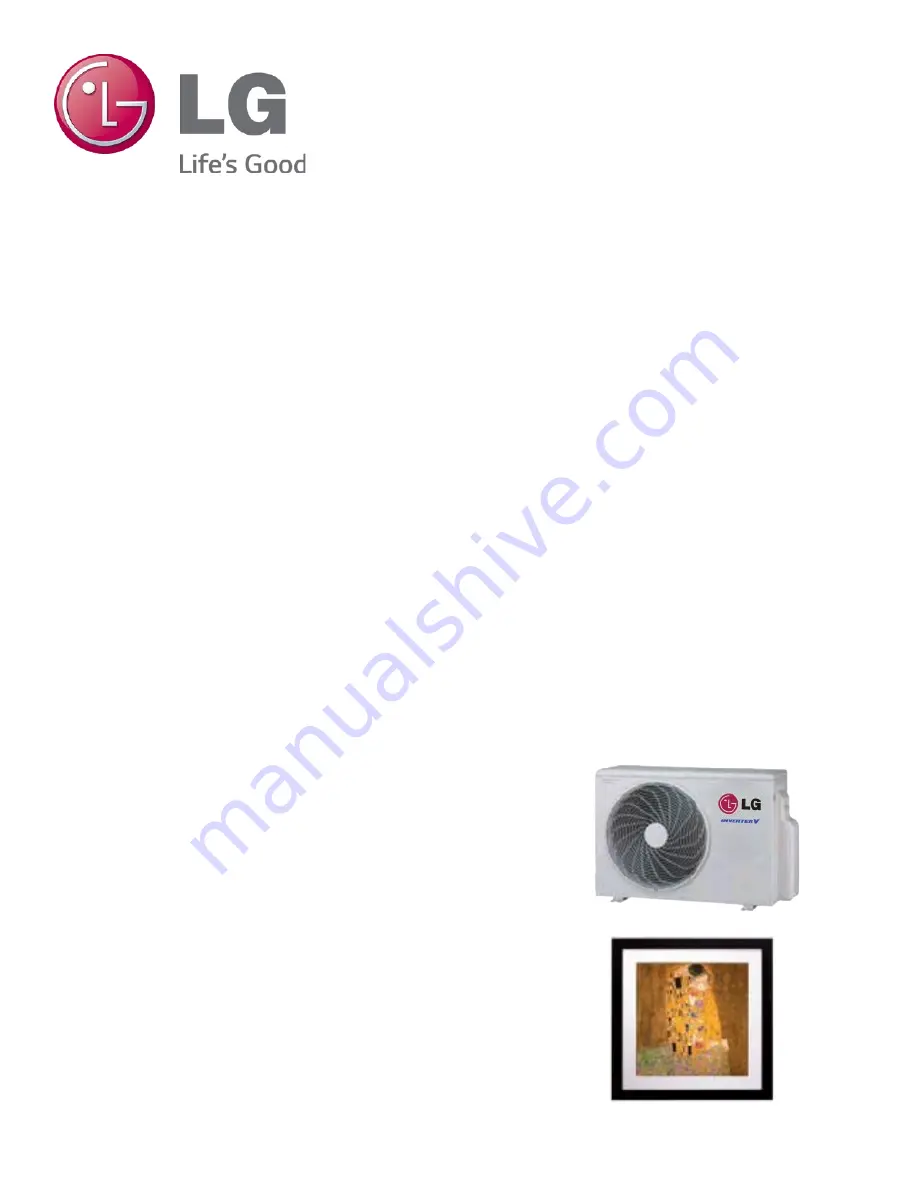
Single Zone Art Cool Gallery Wall Mount: LA090HVP, LA120HVP
Page 1: ...SINGLE ZONE ART COOL GALLERY WALL MOUNTED INSTALLATION MANUAL Single Zone Art Cool Gallery Wall Mount LA090HVP LA120HVP ...
Page 2: ...begins on page 3 For more technical materials such as submittals engineering databooks and catalogs visit www lghvac com For continual product development LG Electronics U S A Inc reserves the right to change specifications without notice LG Electronics U S A Inc This document as well as all reports illustrations data information and other materials are the property of LG Electronics U S A Inc PRO...
Page 3: ...ping system and authorization to do so has been obtained from the commis sioning agent There is a risk of equipment damage refrigerant contamination refriger ant loss physical injury or death Dispose the packing materials safely Tear apart and throw away plastic packaging bags so that children do not play with them and risk suffocation Wear protective gloves when handling equipment Sharp edges may...
Page 4: ...re adequate drainage There is a risk of water leakage and property damage Don t install the unit where it s directly exposed to ocean winds Ocean winds may cause corrosion particularly on the condenser and evaporator fins which in turn could cause product malfunction or inef ficient performance When installing the unit in a low lying area or a location that is not level use a raised concrete pad o...
Page 5: ...gs Loose wiring may overheat at connection points causing a fire physical injury or death Do not change the settings of the protection devices If the pressure switch thermal switch or other protection devices are bypassed or forced to work improperly or parts other than those specified by LG are used there is risk of fire electric shock explosion and physical injury or death Do not supply power to...
Page 6: ...Clean up the site after installation is finished and check that no metal scraps screws or bits of wiring have been left inside or surrounding the unit Do not use this equipment in mission critical or special purpose applications such as preserving foods works of art wine coolers or refrigeration The equipment is designed to provide comfort cooling and heating Oil steam sulfuric smoke etc can signi...
Page 7: ...ng System Layout 28 Refrigerant Piping System Limitations 29 Installation Overview 30 Directional Pipe Formation 31 Drain Hose 32 Outdoor Unit Connections 33 Indoor Unit Connections 34 Bundling and Cutting Line 35 Refrigerant Piping Insulation 36 37 Pipe Sleeves at Penetrations 38 Air Purging 39 Leak Test Soap Method Check 40 Evacuation of Lines 41 Finishing Up Charging 41 Front Panel Assembly Tes...
Page 8: ...Zone Wall Mount Indoor and Outdoor Units LA N 090 HVP 2 Generation 2 Second 3 Third Indoor Outdoor Product HEV Mega HXV Mega 115V HYV Art Cool Premier HVP Art Cool Gallery HSV3 High Efficiency HSV2 Art Cool Mirror HV Standard HLV Extended Pipe Nominal Capacity Nominal cooling capacity in Btu h 090 091 9 000 120 121 12 000 180 181 18 000 240 24 000 307 30 000 360 36 000 Type N Indoor Wall Mount Uni...
Page 9: ...ife to recover recycle reclaim or destroy R410A refrigerant according to applicable regulations 40 CFR Part 82 Subpart F under section 608 of CAA 3 Sound Pressure levels are tested in an anechoic chamber under ISO Standard 1996 4 All power communication cables to be minimum 18 AWG 4 conductor stranded shielded and must comply with applicable and national code Type Art Cool Gallery Art Cool Gallery...
Page 10: ...refrigerant line per indoor unit and a 0 ft level difference between outdoor and indoor units Cooling capacity rating obtained with air entering the indoor coil at 80ºF dry bulb DB and 67ºF wet bulb WB and outdoor ambient conditions of 95ºF dry bulb DB and 75ºF wet bulb WB Heating capacity rating obtained with air entering the indoor unit at 70ºF dry bulb DB and 60ºF wet bulb WB and outdoor ambien...
Page 11: ...om Tons Compressor Qty Compressor A Cool Heat Fan Qty ODU Fan A IDU Fan A MCA A MOP A Art Cool Premier LAU090HVP 3 4 1 6 8 7 6 1 0 25 14 7 10 15 LAU120HVP 1 1 6 8 7 6 1 0 25 14 7 10 15 For component model nos Voltage tolerance is 10 Maximum allowable voltage unbalance is 2 MCA Minimum Circuit Ampacity ODU Fan Outdoor Unit Fan Motor IDU Fan Indoor Unit Fan Motor Maximum Overcurrent Protection MOP i...
Page 12: ... the refrig erant is charged in its gaseous state its composition changes and the system will not work properly R410A Refrigerant 0 Ozone Depleting R410A refrigerant has a higher operating pressure in comparison to R22 refrigerant and therefore all piping system materials installed must have a higher resisting pressure than the materials traditionally used in R22 systems R410A refrigerant is an az...
Page 13: ... airflow fans are not buried by direct heavy snowfall If snow piles up and blocks the airflow the system may malfunction 3 Remove any snow that has accumulated by 4 inches or more on the top of the outdoor unit 4 Place the outdoor unit on a raised platform at least 20 inches higher than the average annual snowfall for the area In environments where there is a possibility of heavy snow the frame he...
Page 14: ...lock any winds Windbreak should be more than 150 of the outdoor unit s height There must be 2ft and 3 1 2 inches clearance between the outdoor unit and the windbreaker for purposes of air flow Additional anti corrosion treatment may need to be applied to the outdoor unit at oceanside locations Ocean winds may cause corrosion particularly on the condenser and evaporator fins which in turn could cau...
Page 15: ...vibration Tie Downs and Wind Restraints The strength of the Duct free Split Single Zone Inverter system frame is adequate to be used with field provided wind restraint tie downs The overall tie down configuration must be approved by a local professional engineer Always refer to local code when designing a wind restraint system Snow and Ice Conditions In climates that experience snow build up place...
Page 16: ...ound the unit Adhere to all clearance requirements if installing the unit on a roof Be sure to level the unit and ensure that the unit is adequately anchored Consult local codes for rooftop mounting requirements Figure 4 Outdoor Unit Clearances Outdoor Unit Clearance 12 28 24 12 24 Unit inch Do not place the unit where animals and or plants will be in the path of the warm air or where the warm air...
Page 17: ...Single Zone Wall Mount Continued Minimum 27 19 32 Minimum 11 13 16 ODU Service Access Clearances Unit Inch In order to have successful service access to the out door unit see Figure 8 for minimum spacing When installing multiple outdoor units see Figure 9 for correct spacing requirements Figure 6 ODU Service Access Clearance Single Unit Figure 7 ODU Service Access Clearance Multiple Units Minimum ...
Page 18: ...right or left bottom side covers and the piping hole knockout in order to pass the drain hose and piping through This procedure should be done after removal of the front panel of the indoor unit Procedure 1 Using a phillips head screwdriver remove the center bottom screw from the L bracket tube holder Figure 8 2 Detach one of the side covers either right or left depending on how you want to place ...
Page 19: ... of the wall This will allow enough room to hang the Gallery unit Select location carefully Unit should be anchored to a strong wall to pre vent unnecessary vibration When choosing a location for the wall mount plate be sure to take into consideration routing of wiring for power outlets within the wall Contacting wiring can cause serious bodily injury or death Use caution when drilling holes throu...
Page 20: ...hole core drill bit drill a hole at either the right or left side of the wall mounting Figure 10 The slant of the hole should be 3 16 to 5 16 from level with the slant being upward on the indoor unit side and downward on the outdoor unit side 2 Finish off the newly drilled hole as shown with bushing and sleeve covering Sleeve and bushing prevents damage to the tubing bundling of the piping See Ref...
Page 21: ...ompletely remove all burrs from pipe ends When removing burrs point the end of the copper pipe down to avoid introducing foreign materials in the pipe 2B Slide the flare nut onto the copper tube Copper tube 90 Slanted Uneven Rough Pipe Reamer Point down Flare nut Copper tube Bar Copper pipe Clamp handle Red arrow Cone Yoke Handle Bar A Slanted Inside is shiny with no scratches Smooth Even length D...
Page 22: ...adation Poor insulation of the compressor System does not operate properly EEVs capillary tubes are clogged Refrigerant oil degradation Poor insulation of the compressor System does not operate properly EEVs and capillary tubes become clogged Refrigerant gas leaks shortages Refrigerant oil degradation Poor insulation of the compressor System does not operate properly Solutions Remove moisture from...
Page 23: ...on valves and other heat sensitive control components from excessive heat with a wet rag or a heat barrier spray product Refrigerant Piping System Insulation All refrigerant piping field provided isolation ball valves service valves and elbows shall be completely insulated using closed cell pipe insulation The liquid and vapor lines must be insulated separately To prevent heat loss heat gain throu...
Page 24: ...dust water or other contaminants from entering the piping during installation Contaminants can cause mechanical failure Selecting Field Supplied Copper Tubing Copper is the only approved refrigerant pipe material for use with Duct Free System Single Zone products and LG recommends seamless phosphorous deoxidized ACR type copper pipe hard drawn rigid type K or L or annealed tempered copper pipe Dra...
Page 25: ...vided to allow pipe expansion to naturally occur The most common method is the inclusion of expansion Loop or U bends Each segment of pipe has a natural fixed point where no movement occurs This fixed point is located at the center point of the segment assuming the entire pipe is insulated in a similar fashion The natural fixed point of the pipe segment is typically where the expansion Loop or U b...
Page 26: ...change in pipe length Pipe Length1 Fluid Temperature F 35 40 45 50 55 60 65 70 75 80 85 90 95 100 105 110 115 120 125 130 10 0 04 0 04 0 05 0 06 0 06 0 07 0 08 0 08 0 09 0 09 0 10 0 10 0 11 0 11 0 11 0 12 0 13 0 14 0 15 0 15 20 0 08 0 08 0 10 0 12 0 13 0 14 0 15 0 16 0 17 0 18 0 19 0 20 0 21 0 22 0 22 0 23 0 26 0 28 0 29 0 30 30 0 12 0 12 0 15 0 18 0 20 0 21 0 23 0 24 0 26 0 27 0 29 0 30 0 32 0 33...
Page 27: ...t and the indoor unit Duct Free Single Zone systems are provided with redundant systems that assure oil is properly returned to the compressor Sight glasses and solenoid valves may cause vapor to form in the liquid stream Over time dryers may deteriorate and introduce debris into the system The designer and installer should verify the refrigerant piping system is free of traps sagging pipes sight ...
Page 28: ...de signed to meet local codes If allowed by code use fiber straps or split ring hangers suspended from the ceiling on all thread rods fiber straps or split ring hangers can be used as long as they do not compress the pipe insulation Place a second layer of insulation over the pipe insulation jacket to prevent chafing and compression of the primary insulation within the confines of the support pipe...
Page 29: ...ant Pipe and Cable s in a Utility Conduit Table 11 Utility Conduit Sizes 1 OD pipe diameter in inches Values in parenthesis indicate OD of pipe with insulation jacket 2 Diameter of pipe with insulation Thickness of pipe insulation is typical Actual required thickness may vary based on surrounding ambient conditions and should be calculated and specified by the design engineer 3 Insulation thicknes...
Page 30: ...in the design of a Single Zone Wall Mount refrigerant pipe system Refer to Figure 22 for maximum length and elevation of piping Table 13 Art Cool Gallery Refrigerant Piping System Limitations Figure 24 Single Zone System Layout Refrigerant Piping System Limitations Pipe Length ELF Equivalent Length of pipe in Feet Longest total equivalent piping length 49 feet Shortest total equivalent piping leng...
Page 31: ...ita tions section on the previous page for specific length limitations in conjunction with outdoor unit and indoor unit positioning A B Pipe Clamps A B 12 19 As you proceed with the piping connections be sure to adhere to pipe support spacing lengths as shown in Figure 26 below Refer back to Pipe Supports section for in depth information regarding using elbows clamps and pipe supporting materials ...
Page 32: ...ing cable from down to up 3 Secure the taped piping along the exterior wall using pipe clamps 4 Create trap above the electrical connections cover in order to pre vent water from penetrating electrical components and wiring Indoor Unit Installed Below Outdoor Unit 1 Refer to Figure 30 while following the procedures below 2 Tape the piping drain hose and connection cable from down to up 3 Secure th...
Page 33: ...ted from the indoor unit through the structure wall to the outdoor It should slope at an angle where it is high er at the indoor unit and lower toward the outdoor area thereby letting gravity push any condensation down and out See Figure 31 for proper drainage slope Avoid piping the drain hose as shown in Figure 32 These methods are incorrect and can cause leakage at the indoor unit site Downward ...
Page 34: ...of refrigerant oil on the opening rim of the flare before assembling Ensure you do not add any contaminants Tighten the flare nut initially by hand 5 Finish tightening the flare nut with a torque wrench until the wrench clicks Follow torque guidelines in Table 14 Figure 33 Outdoor Unit Connection Cover Removal Tubing Cover Bracket for Main Power Cables When tightening the flare nut with a torque w...
Page 35: ...or proper drainage slope during piping procedure 1 From the rear of the indoor unit carefully bend the copper pipe tubing holder away from the unit to expose for conduit bracket installation area Figure 36 Piping and Bundling Indoor Unit 2 Position the bundled tubing by bending slowly downward first as shown in Figure 37 Bending the copper tubing directly left or right without bending downward fir...
Page 36: ...no gaps during the binding 2 Be sure the tube cutting line is placed upward Figure 39 3 Verify that rear piping house section is wrapped with vinyl tape Use a narrow type of vinyl tape for this step 4 Continue to wrap the Indoor unit pipe as connected to the outdoor connection pipe as shown in Figure 40 Figure 38 Piping with Insulation Material Figure 39 Correct Cutting Line Placement Figure 40 Wr...
Page 37: ...n pipe with no air space between it and the pipe Insulation passing through pipe hangers inside conduit and or sleeves must not be compressed Protect insulation inside hangers and supports with a second layer All pipe insulation exposed to direct sunlight and deterioration produc ing elements must be properly protected with a PVC aluminum vapor barrier jacket or alternatively placed in a weather r...
Page 38: ...or a dormitory or school etc Minimum Refrigerant Pipe Ethylene Propylene Diene Methylene EPDM Insulation Wall Thickness Requirements 4 Special location Non Air conditioned location If conditions 1 and 2 below are present 1 When the piping passes through an indoor area where the indoor unit does not operate 2 When the humidity is high and there is no air flow in the location where the piping is ins...
Page 39: ...e resistant insulation When filling an access hole with mortar cover the area with steel plate so that the insulation will not fall through For this area use fire resistant materials for both the insulation and cover Vinyl cover should not be used Pipe Sleeves at Penetrations LG requires that all pipe penetrations through walls floors and pipes buried underground be properly insulated and routed t...
Page 40: ...ging with a Vacuum Pump Preparation Steps 1 Verify that each set of pipes liquid and gas are properly con nected between the indoor and outdoor unit Verify that all wiring for a test run has been completed 2 Remove service valve caps from the gas and liquid valves at the outdoor unit Figure 46 Both the liquid and gas side service valves at the outdoor unit should be kept closed at this step 3 Set ...
Page 41: ...nitrogen gas and close the cylinder valve when the gauge reading reaches 150 P S I G Soap Water Method Leak Testing 1 Remove the caps from the 2 way and 3 way valves See Figure 46 2 To open the 2 way valve turn the valve stem counter clockwise approximately 90 wait for about 2 3 sec and close it 3 While running the nitrogen gas tank hookup apply a soap water or a liquid neutral detergent on the in...
Page 42: ...p Refer to Table 16 for accurate time duration 4 Turn off the pump and leave the connections secured to the two service valves 5 Wait 5 minutes 6 If the system fails to hold 500 microns or less check all connec tions for tight fit and repeat the evacuation procedure 7 Once desired vacuum is reached close the Lo knob of the manifold valve and stop the vacuum pump 8 Proceed to Finishing the Job sect...
Page 43: ... panel to the Single Zone Art Cool Gallery indoor unit Before placing the front panel be sure that all electrical wiring is connected between the outdoor and indoor unit Doing a test run requires that the system be in operational condition regarding all piping and electrical connection If you have not done electrical hookup proceed to the electrical connection section in this manual and then come ...
Page 44: ...atteries have clicked into the compartment and are firmly engaged with the contacts on either side of them 4 Reattach the back cover of the remote controller 5 Proceed with powering on the remote controller and usage as needed 1 Push down on tab 2 Lift cover 3 Insert 3 batteries Single Zone Remote Controller Rear View Battery Cover Tab Battery Cover Figure 49 Remote Controller Installing Batteries...
Page 45: ...unit off Pump down procedure is complete at this time and all refrigerant should be collected into the outdoor unit Enabling Cooling Only Mode Before running the Pump Down procedure you must place the unit into Cooling Only Mode In order to be able to run Cooling Only Mode you must enter the unit into the Installer Mode by pressing the Reset button and the JET MODE button simultaneously 1 Shut dow...
Page 46: ...ne outdoor and indoor unit Ground wiring is required to prevent accidental electrical shock during cur rent leakage Ground wiring must always be installed by a qualified technician Do not connect ground wire to refrigerant gas or water piping to lightning rods to telephone ground wiring or to the building plumbing system Failure to properly provide a National Electrical Code approved earth ground ...
Page 47: ...Wiring and Communications Cable Diagram Copper Wire Terminate multiple power wires of the same gauge to both sides Do not terminate two wires on one side Do not terminate different gauge wires to a terminal block Ring Terminal Power Wiring Connecting the Power Wiring Guidelines Best practice dictates using ring or spade terminals to terminate power wiring at the power terminal block Figure 52 If r...
Page 48: ...Minimum 18 gauge shielded CVVS or CPEVS cable Insulation material as required by local code Rated for continuous exposure of temperatures up to 140 F Maximum allowable cable length 984 feet Firmly attach the cable provide slack but secure in a way to pre vent external forces from being imparted on the terminal block Wiring should be completed without splices Terminate the cable shield to a grounde...
Page 49: ...le 20 as to which remote controller models to use for each Single Zone model Once all wiring is connected to the indoor and outdoor units be sure to test the accompanying remote controllers for performance As always follow all safety warnings and notes when operating the Single Zone units using the remote controller Table 20 Single Zone Model and Associated Remote Controller Model Additionally mos...
Page 50: ...oming from the outdoor unit will be connected to this power cord Pay attention to the location connection of the green yellow ground cable See Figure 57 on page 51 for proper installation between the outdoor and indoor unit 2 Once electrical wiring is completed refer back to Front Panel Assembly Test Run on page 43 before running a test on the system 3 If all other piping and electrical wiring to ...
Page 51: ... 57 ArtCool Gallery Terminal Block Wiring Diagram Procedure Refer to Figure 55 regarding how a circuit breaker should be wired through to the Single Zone system Be sure there is no power going through the Single Zone system before proceeding with these connections as it may result in electric shock Familiarize yourself with the location of the circuit breaker and be sure that all power is cut to t...
Page 52: ...compressor discharge temperature Front outdoor coil pipe temperature Back outdoor coil pipe temperature Liquid line pipe temperature Subcooler inlet temperature Subcooler outlet temperature Average indoor unit IDU pipe temperature Inverter compressor operation indicator light Liquid injection valves operation indicator lights Hot gas bypass valve operation indicator light Four way reversing valve ...
Page 53: ... RS 485 connector kit When connected through IDU user will not be able to record data This software can be used to both commission new systems and troubleshoot existing systems LGMV data can be recorded to a CSV file and emailed to an LG representative to assist with diagnostic evaluations Recommended Minimum PC Configuration Error Codes LGMV software helps the service technician or commissioning ...
Page 54: ...also be used with Single Zone one to one configurations such as the Single Zone Wall Mount systems The Duct Free System air conditioning system must run for at least 15 20 minutes before data collected by SIMs 2 0 is valid for troubleshooting You must have the free SIMs app correctly in stalled on your smart phone before using SIMs Some ODUs have an LGMV extension cable ac cessed by removing the s...
Page 55: ...tart Timer Comp Mode EEV Indoor Info Tab Displays the following information Frequency Operation THM Mode REM Mode FAN EEV Air Temp Pipe in Pipe mid Pipe out Graph Info Tab This tab has three sub sections IDU Indoor Unit Temperature graph Displays IDU informa tion in graph format In formation displayed is for the IDU selected on the Main screen ODU Outdoor Unit Temperature and Fre quency graph Disp...
Page 56: ...ED2 Red light 1x blink Error Code Nomenclature Definitions MICOM Non volatile memory chip where unit setup information is stored EPROM Non volatile memory chip where device identification size and factory defined default component operating parameters are stored Error Code Description 1 Indoor unit room temperature sensor error 2 Indoor unit inlet pipe sensor error 4 Float switch error optional 5 ...
Page 57: ... units Table 22 Single Zone Wall Mounted Outdoor Unit Error Codes Error Code Description No of Times Outdoor Unit LEDs Blink LED1 Plasma LED LED2 Power LED 21 DC Peak IPM Fault Compressor DC voltage was too high 2X 1X 22 Current Transformer2 CT2 error Alternating current AC input too high 2X 2X 23 DC Link Low Volt 2X 3X 25 AC Low High Volt 2X 5X 26 DC Comp Position Error not providing rotation Loc...
Page 58: ...full description of all error codes and work arounds Error Code Description No of Times Outdoor Unit LEDs Blink LED1 Plasma LED LED2 Power LED 61 Outdoor unit condenser coil temperature is too high 6X 1X 62 Outdoor unit inverter compressor PCB heat sink temperature is too high 6X 2X 63 Condenser coil pipe thermistor temperature is too low 6X 3X 65 Heat sink thermistor has disconnected or has short...
Page 59: ... do so can cause health hazards and bodily injury to occupants of the space 1 American Society of Heating Refrigeration and Air Conditioning Engi neers Inc ASHRAE Atlanta GA ASHRAE Inc Information about ASHRAE Standard 15 2010 34 2010 and addenda current as of the date of this publication Take appropriate actions at the end of HVAC equipment life to recover recycle reclaim or destroy R410A refrige...
Page 60: ... and hangers Brazing Practices Description Check Medical grade there are 4 available dry nitrogen for purging during brazing was used constant 3 psi while brazing Installation For more information on any procedure refer to the detail provided in the Indoor Unit Installation Manuals Refrigerant Piping Description Check All pipe materials were properly stored capped and cleaned All burrs were remove...
Page 61: ...ll local electrical code requirements Power wiring to the indoor unit was installed per all local electrical code requirements LG supplied cable was used between the indoor unit and its zone controller No cables were spliced and no wire caps are present Communication type RS 485 BUS type All communications cables were a minimum of 18 AWG four 4 conductor shielded and stranded with insulation mater...
Page 62: ...1405 Old Roswell Road Alpharetta Georgia 30009 www lghvac com IM SZ ArtCoolGallery LA090HVP_LA120HVP 11 14 LG Customer Information Center Commercial Products 1 888 865 3026 USA Follow the prompts for commercial A C products 20001747 ISO 9001 2008 LG ELECTRONICS INC ...