


49
Electrical System Installation
Due to our policy of continuous product innovation, some specifications may change without notification.
©LG Electronics U.S.A., Inc., Englewood Cliffs, NJ. All rights reserved. “LG” is a registered trademark of LG Corp.
ELECTRICAL
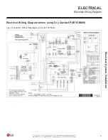
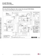
Communication Cable Specifications
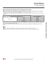
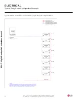
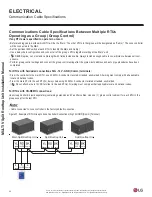
Communications Cable Specifications from RTUs to Remote Controllers
• Communication cable from RTU to Remote Controller(s) is to be LG supplied or field supplied 22 AWG, 3-conductor, twisted, stranded,
unshielded. Wiring must comply with all applicable local and national codes.
• If using LG supplied cable and the length needs to be extended, the LG Extension Kit (sold separately) must be used. A maximum of four
(4) kits (up to 165 feet) can be used.
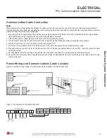
• Remote Controllers have hardwired connections: SIG - 12V - GND (Comm.) terminals.
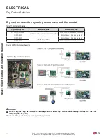
• See diagrams below for two options: terminal block connections and Molex connections. Refer to the wiring diagram schematic found in the
RTU itself, or to the wiring diagram in this Manual.
•
NEVER splice, cut, or extend cable length with field provided cable. Always include enough cable to cover distance between the RTU
and the remote controller.
• Set the RTU operating parameters using DIP switches, or by setting up the remote controller. Refer to the remote controller installation
manuals for more details.
Cable connected to Zone Controller is the factory default connection.
Figure 35: One Example of RTU to Zone Controller Connection.
BACnet-
BACnet Common
Not used
Not used
Not used
Common
4 5 6
13 14 15
Split Rooftop Unit
Signal
12VDC
YL
RD
BK
CN-REMO
R D
B K
Y L
Front
CN-REMO
R D B K
Y L
Back
Split Rooftop Unit
Figure 36: Another Example of RTU to Zone Controller Connection.