background image


Due to our policy of continuous product innovation, some specifications may change without notification. 

©LG Electronics U.S.A., Inc., Englewood Cliffs, NJ. All rights reserved. “LG” is a registered trademark of LG Corp.


34 

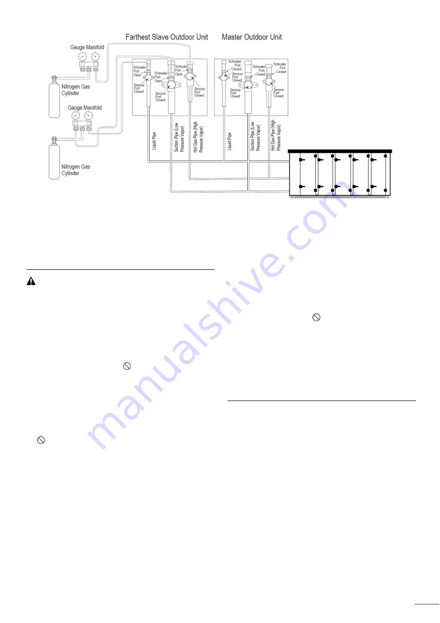
Figure 17: Leak / Pressure Test for system designed for DOAS 


Evacuation 

After the leak / pressure check is complete, perform a 
Triple Evacuation with the entire system. Evacuation 
must be performed through the Schrader ports on the 
outdoor unit service ports.


WARNING 

• 

For faster evacuation, the Schrader core can be removed, 
and an auxiliary service port can used. Make sure to re-
install the original Schrader core before operating the 
system.   

• 

For Heat Recovery systems, evacuate through all three (3) 
hot gas line (high pressure vapor), liquid line, and suction 
(low pressure vapor) refrigerant lines. 

• 

The outdoor unit service valves must remain closed and the 
stem head access caps tight.      Do not open the outdoor 
unit service valves and release the factory refrigerant 
charge until the LG trained commissioner authorizes to do 
so. The system must be left in vacuum until the LG trained 
commissioner verifies the quality of the evacuation. 

• 

Any field-installed ball valves in the refrigerant system (if 
used) must be open to ensure all piping is free and clear for 
evacuation on all piping and connected DOAS units 

• 


Do not apply power to the units before performing a 

system leak test. There is a possibility that the EEV valves 
will close and isolate sections of the piping system, making 
the leak test inconclusive. Contact your LG Applied Rep or 
service technician for the procedure to reopen the EEV 
valves before the leak test ONLY if the power has been 
applied 

• 

For multi-frame outdoor units, connect the vacuum pump / 
manifold to the service port Schrader ports (or core) to only 
one outdoor unit, preferably the slave outdoor unit that is 
installed farthest away from the refrigerant piping system 
and connected DOAS units 

• 

Use only a vacuum pump that can reach 500 microns, 
vacuum rated hoses or copper tubing, and a leak-free 
gauge manifold set 

• 

Use only new vacuum pump oil from a properly sealed 
(unopened) container, and change oil in pump before 

EVERY

 use. 

• 

Subsequent oil changes will be necessary after several 
hours of continuous operation; have extra oil on hand. 

• 

Use a quality micron gauge in good operating order and 
install as far away from pump as possible 

• 

Connect the vacuum pump to the gauge manifold and 
hoses. Once the vacuum pump is first operated, if hoses, 
manifold, and vacuum valves are leak free (and oil is no 
moisture laden), the gauge must read <100 microns within 
on (1) minute. 

• 

Use a vacuum pump or Inert (nitrogen) gas when doing 
leakage test or air purge.      Do not compress air or Oxygen 
and do not use Flammable gases. Otherwise, it may cause 
fire or explosion. There is the risk of death, injury, fire or 

explosion

.


• 

If the outdoor unit is moved to and installed in another site, 
only charge with new refrigerant after successful leak test 
and triple evacuation procedures have been performed. If 
different refrigerant or air is mixed with the original 
refrigerant, the refrigerant cycle will malfunction and the unit 
will be damaged.


Summary of Contents for ARND30UDBE4

Page 1: ... performed in accordance with the national wiring standards by authorized personnel only Please retain this installation manual for future reference after reading it thoroughly www lghvac com www lg com Copyright 2021 LG Electronics Inc All Rights Reserved ENGLISH MFL71812201 Rev 00_210118 LG SPLIT ROOFTOP DEDICATED OUTDOOR AIR SYSTEM DOAS ...

Page 2: ...Electronics U S A Inc and are disclosed by LG Electronics U S A Inc only in confidence This document is for design purposes only A summary list of safety precautions is on page 4 To access additional technical documentation such as submittals installation service general best practice and building ventilation manuals as well as white papers catalogs software programs and more log in to www lghvac ...

Page 3: ... Condensate Drain Connection 23 Refrigerant Piping Installation 23 General Information 23 Selection of Field Supplied Piping Material 23 Piping Handling 24 Refrigerant System Engineering 24 Selection of Piping Size 24 Selection of Refrigerant Y Branch Kits 25 Braze Procedure 26 Refrigerant Pipe Insulation 27 ELECTRICAL INFORMATION 28 Field Wiring 28 Determine the Size of the Main Power Line 28 Pow...

Page 4: ...ation LG Electronics U S A Inc Englewood Cliffs NJ All rights reserved LG is a registered trademark of LG Corp 4 IP Address 42 DOAS Unit Address Setting 42 Central Controller Setting 43 Main Control Board Terminal Connections 46 CAREL Control Board Terminal Connections 46 LG Control Board Layout 47 ...

Page 5: ...of an installed unit always contact a trained service provider There is risk of fire electric shock explosion and physical injury or death Periodically check that the unit is not damaged There is risk of explosion physical injury or death Replace all control box and panel covers If cover panels are not installed securely dust water and animals may enter the unit causing fire electric shock and phy...

Page 6: ... equipment life to recover recycle reclaim or destroy R410A refrigerant according to applicable U S Environmental Protection Agency EPA rules Install the unit in a safe location where no one can step on or fall onto it There is risk of unit and property damage Install the drain trap to ensure adequate drainage There is a risk of water leakage and property damage Always check for system refrigerant...

Page 7: ...h the proper tools and test instruments Failure to carefully read and follow all instructions in this manual can result in injury death or equipment malfunction or property damage Ensure the unit is connected to a dedicated power source that provides adequate power If the power source capacity is inadequate or the electric work is not performed properly it may result in fire electric shock physica...

Page 8: ...d connection for damage Cable must be replaced by the manufacturer its service agent or similar qualified persons in order to avoid physical injury and or electric shock Securely attach the electrical cover to the unit Non secured electrical covers can result in burns or electric shock due to dust or water in the service panel Ensure no power is connected to the unit other than as directed in this...

Page 9: ...olicy of continuous product innovation some specifications may change without notification LG Electronics U S A Inc Englewood Cliffs NJ All rights reserved LG is a registered trademark of LG Corp 9 PRODUCT OVERVIEW ...

Page 10: ...ntinuous product innovation some specifications may change without notification LG Electronics U S A Inc Englewood Cliffs NJ All rights reserved LG is a registered trademark of LG Corp 10 CONTROL BOX OVERVIEW HR BOX OVERVIEW ...

Page 11: ...Rows x Columns x FPI x L Reheat coil 2 x 28 x 14 x 940 Rows x Columns x FPI x L Recovery coil 2 x 28 x 14 x 940 Fin Type LG Wide Louver Corrosion Protection Black Coated Fin Material Tube Fin CU AL Tube Diameter Thickness Φ mm 7 0 25 Dimensions W x D x H Body Inch 151 5 x 64 x 57 3 mm 3848 x 1455 x 1626 Weight Body lbs 2326 kg 1055 Air Filter Hood 1 Aluminium mesh Supply 2 MERV 8 25 x 20 4EA Retur...

Page 12: ...G is a registered trademark of LG Corp 12 ELECTRICAL DATA Capacity ton Unit FLA Power Supply Hz Volts Supply Fan Exhaust Fan Wheel MCA MOP MOCP 10 60 460 5 9 5 4 0 5 13 3 19 2 20 60 203 230 11 10 1 24 8 35 8 35 MCA Minimum Circuit Ampacity MOCP Maximum Over Current Protection Largest motor FLA x 2 25 Sum of other motor FLA rounded down to the nearest standard fuse size ...

Page 13: ...ications may change without notification LG Electronics U S A Inc Englewood Cliffs NJ All rights reserved LG is a registered trademark of LG Corp 13 ELECTRICAL WIRING DIAGRAM Fan Motor SA Fan Motor EA UNASSIGNED N L2 L L1 L L1 N L2 L L1 L L1 N L2 N L2 N L2 L L1 L ...

Page 14: ...G DEHUMIDIFICATION 14 High Temperature High Pressure Vapor Low Temperature Low Pressure Vapor High Temperature High Pressure Liquid Main Coil 2 S S S S S EEV S S Main Coil 1 EEV Reheat Coil EEV Recovery Coil EEV S SA OA RA S S S EA High Temperature High Pressure Vapor Low Temperature Low Pressure Vapor High Temperature High Pressure Liquid Main Coil 2 S S S S S EEV S S Main Coil 1 EEV Reheat Coil ...

Page 15: ...nics U S A Inc Englewood Cliffs NJ All rights reserved LG is a registered trademark of LG Corp HEATING 15 High Temperature High Pressure Vapor Low Temperature Low Pressure Vapor High Temperature High Pressure Liquid Main Coil 2 S S S S S EEV S S Main Coil 1 EEV Reheat Coil EEV Recovery Coil EEV S SA OA RA S S S EA ...

Page 16: ... Sound Intensity Tests conducted in accordance with this standard Free field measurement plane created 1 foot from unit on Supply Return side and Top Reference acoustic intensity 0dB 10E 6μW m2 A Weighted Sound Power was determined using AMCA standard 301 90 Clause 9 1 Measured dB 3 000 CFM 1in Wg 90 8 86 4 80 8 78 5 76 1 70 9 68 4 20 30 40 50 60 70 80 90 100 125 250 500 1000 2000 4000 8000 Sound ...

Page 17: ...manufacturer will not be responsible for damage during storage These suggestions are provided solely as a convenience to the user The ideal environment for the storage of units and accessories is indoors above grade in a low humidity atmosphere which is sealed to prevent the entry of blowing dust rain or snow Units designed for outdoor applications may be stored outdoors Indoor Maintain temperatur...

Page 18: ...ers Motorized intake air damper motorized recirculating damper and motorized exhaust damper Filters One inch thick aluminum mesh filters in the outdoor weather hood 2 inch thick pleated paper MERV 8 standard or MERV 13 filters in the supply air stream 4 inch thick filter bank with a 2 inch thick MERV 8 and 2 inch thick MERV 13 or a 4 inch thick MERV 14 pleated paper supply filters Split DX system U...

Page 19: ...t cabinet Avoid twisting or uneven lifting of the unit The cable length from the bracket to the hook should always be longer than the distance between the outer lifting points Lifting 1 Before lifting be sure that all shipping materials have been removed from unit 2 To assist in determining rigging requirements weights are provided in the Unit Weights Dimensions section of this manual 3 Spreader b...

Page 20: ...ibility of the system designer to make adequate provisions for noise and vibration in the occupied space Install the curb and unit level to allow the condensate drain to flow properly and allow service access doors to open and close without binding Roof curb details including duct locations and dimensions are to be found in the roof curb assembly instructions Rooftop units require curbs to be moun...

Page 21: ...D 2 6 ALUMIMUM FILTER 2 7 INSULATION 4 The outdoor air hood have only one row of aluminum filters The outdoor air hood parts are located at the bottom of the unit Hood Installation 1 Remove and discard the shipping foam or tape 2 Remove and take inventory of parts shipped in the sill of the opening 3 Install the Left and Right side triangle support 4 Install the Hood Left Right Side Triangle suppo...

Page 22: ... the unit and the building ducts Duct connections to collar type openings can be made with S cleats or overlapping joints Apply caulk around each duct connection Failure to seal duct connections can cause air leakage and system performance problems A straight duct for a distance of three 3 to six 6 duct diameters from the unit discharge should be used to develop a full dynamic head Branching and t...

Page 23: ...ations Refrigerant Piping Installation This product is designed to work with refrigerant R410A Always follow these instructions to perform installation procedures Be sure to use the specified refrigerant during refrigerant circulation and prevent air from contaminating the refrigerant If the refrigerant leaks during the installation process make sure to ventilate any enclosed space Pipes should be...

Page 24: ...er than or equal to the slave2 outdoor unit capacity Connection piping from branch to branch cannot exceed the main pipe diameter A used by the outdoor unit Install the header branches or heat recovery units so that the pipe distances between the between the connected indoor units are minimized Large differences in pipe distances can cause indoor unit performances to fluctuate Y branches and other...

Page 25: ...eader is not allowed in DOAS Application For Y Braches other than the first branch select the proper branch kit model based on the total capacity of all DOAS units connected after the refrigerant Y Branch kit model can be changed by DOAS unit combination and Outdoor unit selection Please refer the LATS HVAC software selection Table 9 System Piping Length Length Total Pipe Length Longest actual pip...

Page 26: ...at can easily become blocked Proper system operation depends on the installer using best practices and utmost care while assembling the piping system 2 Store pipe stock in a dry place keep stored pipe capped and clean 3 Blow clean all pipe sections with dry nitrogen prior to assembly 4 Use adapters to assemble different sizes of pipe 5 Always use a non oxidizing material for brazing Do not use flu...

Page 27: ...imum thicken 9 16 in If the ambient temperature exceeds 86 F and the humidity 80 RH then the minimum thickness is 3 4 in Ethylene Propylene Diene Methylene EPDM Insulation must be a minimum 1 2 inches thick and thickness will need to be increased based on ambient conditions and local codes All insulation joints must be glued with no air gaps Insulation material must fit snugly against the refriger...

Page 28: ...here is also equipment malfunction and property damage Do not connect ground wire to refrigerant gas or water piping to lightning rods to telephone ground wiring or to the building plumbing system Failure to properly provide a NEC approved earth ground can result in electric shock physical injury or death There is also equipment malfunction and property damage Consider ambient conditions temperatu...

Page 29: ...attached there is risk of fire electric shock explosion physical injury or death There is also equipment malfunction and property damage Never apply line voltage power to the communications cable terminal block If contact is made the PCBs will be damaged Always include some allowance in the wiring length when terminating Firmly attach the wiring or cable but provide some slack to facilitate removi...

Page 30: ...Master ODU to Slave ODU s and Master ODU to DOAS to be 18AWG 2 conductor twisted stranded shielded Ensure the communication cable shield is properly grounded to the Master ODU chassis only Do not ground the ODU to DOAS communication cable at any other point Wiring must comply with all applicable local and national codes Inadequate connections may generate heat cause a fire and physical injury or d...

Page 31: ...d in the space served by the ventilator at a height of approximately five 5 feet from the floor Two 2 individual sensors are provided to prevent interference but the individual enclosures may be installed on a wall immediately next to each another Wiring between the unit and the temperature sensor must be through a field supplied 18AWG 2 or 3 conductor twisted stranded Terminations must be made pe...

Page 32: ...following chart Sensor setting LG recommend CO2 Sensor 0 10Vdc Honeywell C7232A1008 Table 13 Space CO2 Sensor Termination Main Module Space CO2 Sensor Type 0 10Vdc Terminal Strip TB Main Module UI8 G Figure 20 CO2 sensor connection 0 10Vdc Differential Pressure Sensor Exhaust When a unit is designed with Air Volume CFM Control at exhaust fan A differential pressure sensor is needed to be supplied ...

Page 33: ... in the piping system 2 Verify that all outdoor unit service ports are closed For multi frame outdoor units verify the service valves on all master and slave outdoor units are closed and the stem head access caps are tight The leak pressure check is to be performed to only the refrigerant piping system and connected DOAS units 3 Remove the caps on the Schrader ports Connect the medical grade dry n...

Page 34: ...ng system making the leak test inconclusive Contact your LG Applied Rep or service technician for the procedure to reopen the EEV valves before the leak test ONLY if the power has been applied For multi frame outdoor units connect the vacuum pump manifold to the service port Schrader ports or core to only one outdoor unit preferably the slave outdoor unit that is installed farthest away from the r...

Page 35: ...vacuation back down to 2 000 micron level If the micron level holds at 2 000 micron continue to step 4 4 Break vacuum with 50 psig nitrogen purge for an appropriate amount of time this is to sweep moisture from piping 5 Purge nitrogen from the system until the pressure drops down to 1 to 3 psig 6 Evacuate to 1 000 micron level Isolate the pump by closing the manifold gauges and the vacuum pump val...

Page 36: ...gerant must be treated according to the applicable legislation To avoid compressor breakdown Do not charge the refrigerant more than the specified amount Refrigerant Charge Worksheet The calculation of the additional charge should take into account the length of pipe and CF Correction Factor value of DOAS unit System Tag or ID Job Name _____________________________________________ Project Manager ...

Page 37: ...wiring Be sure that the field wiring has been carried out according to the instructions described in Field Wiring according to the wiring diagrams and according to the applicable legislation 3 Power supply voltage Check the power supply voltage on the local supply panel The voltage must correspond to the voltage on the identification label of the unit 4 Ground wiring Be sure that the ground wires ...

Page 38: ...e wheel causing an excessive pressure drop then wheel cleaning should be performed as follows 1 Using a standard shop vacuum vacuum any debris from both faces of the wheel Slowly work around the entire face of the wheel to complete the procedure Do not damage wheel face by excessive pressure of the vacuum nozzle on the wheel face 2 Using 20 psig clean dry air and a small air nozzle blow air throug...

Page 39: ...just the take up idler s to minimum travel position to accommodate later belt adjustment and retensioning 2 Determine direction of drive rotation CW or CCW Belt must travel with tabs trailing 3 Work the belt through the system going from pulley to pulley The belt should be installed with as little slack as possible leaving just enough length to allow the belt to be installed on the pulleys 4 Deter...

Page 40: ...LG is a registered trademark of LG Corp 40 6 Install and tension the belt There are two methods to achieve proper tension in the belt Remove 1 2 of belt from the hand tight length and the conveyor s take up mechanism Depending on the particular configuration of the conveyor either one of these methods or a combination of the two may be appropriate to tension the belt ...

Page 41: ...y If there is seasonal debris in the air which can be drawn into the filters and the coils they should be checked more frequently If the system is being used for only a few hours per day the frequency may be reduced Use the maintenance log at the end of this manual to record each maintenance session and observations and then establish a maintenance schedule that is appropriate for the installation...

Page 42: ... UI software The controller also provides user feedback through an optional handheld keypad display hardwired or can be connected to a building management system interface Electrical Specifications The DOAS controller receives 24 VAC CAREL and 12VDC LG controller power from a transformer and SMPS on the main control panel and is energized when the main disconnect is on Connecting to the Web UI To ...

Page 43: ...n Settings Date Time Timezone screen Altitude Go to the Main Ctrl Variables Advanced Unit Setting screen IP Address Go to the Main Settings Network Settings screen BMS AC Smart Communication Go to the Main Ctrl Variables Advanced Network Settings screen to set up network communication To communicate with ACP AC Smart Modbus Slave Address must be set and ACP AC Smart should be set to MODBUS protoco...

Page 44: ...nal codes Figure 39 DOAS controller to Central Controller Connections 2 On the CAREL controller under SVC Configuration Network Setting set the Modbus Slave Address as For ARND DB DOAS models CAREL Modbus Slave Address 17 Hex and AC Smart or ACP Address 11 Hex For ARND DC DOAS models CAREL Modbus Slave Address 18 Hex and AC Smart or ACP Address 12 Hex Figure 39 Device I D Screen AC SMART ACP Contr...

Page 45: ...le devices After all necessary units are selected click Apply 5 Click Send All to finish adding the device s 6 Under the AC Smart ACP Control tab find and select Device Control 7 Find the Installation tab and select AC Smart A list of devices available for view will appear in the middle of the screen 8 Click on the device to be viewed A new section will appear on the right side of the screen Click...

Page 46: ...notification LG Electronics U S A Inc Englewood Cliffs NJ All rights reserved LG is a registered trademark of LG Corp BMS Configuration BMS configuration need the Setting Below Device Instance Modbus Slave Address Figure39 BMS Configuration BACnet IP Figure38 BMS Configuration Modbus RTU 46 ...

Page 47: ...ontrol boards and indicate DI Digital Inputs DC Normal Close DO Normal Open DO Digital Outputs DC Normal Close DO Normal Open AI Analog Inputs AO Analog Outputs UI Universal Inputs UO Universal Outputs RI Resistance Input CAREL Control Board Terminal Connections See image below for general board layout See the tables on the following pages for standard terminal connection points See the wiring sch...

Page 48: ...0 UI5 Differential Pressure Sensor For SA flow rate monitoring CFM Modulation 0 10Vdc 0 30 wc UI6 Differential Pressure Sensor Field Options For EA flow rate monitoring CFM Modulation 0 10Vdc UI7 Unassigned UI8 Space CO2 Sensor Field Option 0 10Vdc 0 3000ppm 4 DI1 Forced Stop NC Open Unit Stop DI2 Unit Enable Disable NO Closed Unit On DI3 Float Switch NC Open Unit Stop 5 AO1 Outside Damper output ...

Page 49: ... UI3 Recirculation Damper input Damper position feedback 0 10Vdc 0 100 UI4 Unassigned UI5 Space Return Duct Temperature Field Option 0 10Vdc 130 210F UI6 Space Return Duct Relative Humidity Field Option 0 10Vdc 130 210F Figure42 NTC Module Drawing Reference Label Unit Connection8 Sensor Type Position Indicates Range 2 CH1 CH1 port of Other module for communication RS485 3 RI1 Space Return Duct Tem...

Page 50: ...RS485 CH2 IDU_Bus_A B RS485 3 RI1 Reheat Coil Refrigerant temperature Pipe In NTC 5k 130 210F RI2 Reheat Coil Refrigerant temperature Pipe out NTC 5k 130 210F 4 EEV1 Unassigned EEV2 Reheat Coil EEV Step Control 0 1350 3 Recovery Coil Drawing Reference Label Unit Connection Type Position Indicates Range 2 CH1 CH1 port of Other module for communication RS485 CH2 IDU_Bus_A B RS485 3 RI1 Recovery Coil...

Page 51: ...nts Your LG Manufacturer Representative Wrong Unit Model Your LG Manufacturer Representative Installation Startup and Commissioning Technical Assistance Your LG Manufacturer Representative For warranty information visit www lghvac com CAUTION The Limited Warranty is void and of no effect and LG will have no liability hereunder to any Customer or third party to the extent any of the following occur...

Page 52: ... of continuous product innovation some specifications may change without notification LG Electronics U S A Inc Englewood Cliffs NJ All rights reserved LG is a registered trademark of LG Corp IM_RooftopDOASunit_01_21 52 ...

Page 53: ...US Please call the installing contractor of your product as warranty service will be provided by them ...

Reviews: