background image

19

Installation 

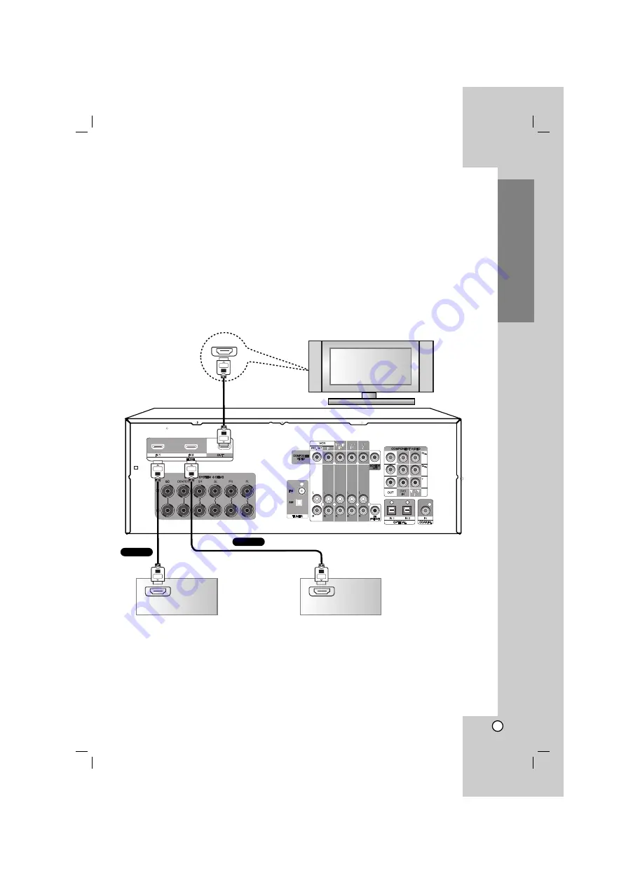
Connecting TV or components with HDMI jack

HDMI (High Definition Multimedia Interface) supports both video and audio on a single digital connection for an easy
all- digital output to an HDMI or DVI-equipped TV.

Connection to an HDMI TV requires an HDMI cable while connection a DVI-equipped TV requires a DVI adapter
besides a HDMI cable.

HDMI has the capability to support standard, enhanced, or high-definition video plus standard to multi-channel
surround-sound audio, HDMI features include uncompressed digital video, a bandwidth of up to 5 gigabyte per
second, one connector (instead of several cables and connector), and communication between the AV source and
AV devices such as DTVs.

HDMI, the HDMI logo and High-Definition Multimedia Interface are trademarks or registered trademarks of HDMI
licensing LLC.

If you have a HDMI TV or monitor, you can connect it to this unit with a HDMI cable.

Notes

• The arrow on the cable connector body should face up for correct alignment with the connector on the unit.

• Don’t connect a TV or MONITOR to HDMI 1/2 jacks. The unit may malfunction. 

• When the multi channel input is used, the real output may be different from the speaker indicators that appear

in display window. (Multi channel : A mode that can be inputted and outputted up to 6.1ch.)

HDMI IN

HDMI compatible TV

Component with HDMI jack

HDMI OUT

Additional component 
with HDMI jack

HDMI OUT

+

-

HDMI

HDMI

Summary of Contents for AR702BR

Page 1: ...S Main Unit AR702TS DD Speakers SR72TS F SR72TS C SR72TS L SR72TS B SR72TS A AR702BR Main Unit AR702BR DD Speakers SR72BR L SR72BR B SR72BR S SR72BR A AR702NS Main Unit AR702NS DD Before connecting operating or adjusting this product please read this instruction booklet carefully and completely AR702TT DD DESPLL_ENG_2925 ...

Page 2: ...ner s manual to be certain Do not overload wall outlets Overloaded wall outlets loose or damaged wall outlets extension cords frayed power cords or damaged or cracked wire insulation are dangerous Any of these conditions could result in electric shock or fire Periodically examine the cord of your appliance and if its appearance indicates damage or deterioration unplug it discontinue use of the app...

Page 3: ...the audio signal 26 Switching the video signal 26 Playing music files using the USB feature 27 Using iPod 28 Playing music files using the PC Link 28 29 Listening to FM AM radio 29 Presetting radio stations 29 RDS Operation 30 Setting the Display Brightness 31 Using the Mute Function 31 Using the Sleep Timer 31 Displaying Source Information 31 Selecting setup menu 32 35 Setup Configuration 32 Gene...

Page 4: ...th this unit Read this before operation Symbol Used in this Manual Note Indicates special notes and operating features Tip Indicates tips and hints for making the task easier Required cables The hookup diagrams on the subsequent pages assume the use of the following connection cables You must purchase the connection cables separately if necessary Analog audio cable iPod cable Analog audio Composit...

Page 5: ...s the input mode ANALOG COAXIAL OPTICAL 1 2 3 Selects HDMI 1 or HDMI 2 on the HDMI mode 13 FM AM Selects the unit s tuner FM and AM bands 14 SURROUND MODE Selects various surround effect 15 DSP Digital Signal Processor Selects DSP Digital Signal Processor mode 16 BYPASS Selects BYPASS mode 17 SETUP Accesses or removes the setup menu 18 b B v V left right up down Selects an item in the menu ENTER A...

Page 6: ...ONENT VIDEO TV STB IN Connect a satellite tuner or set top box etc with component video out jacks to COMPONENT VIDEO TV STB IN jacks 11 SPEAKER SYSTEM Connect the speakers 12 AM ANTENNA Connect an AM antenna 13 FM ANTENNA Connect a FM antenna 14 SW PRE OUT Connect the active subwoofer 15 OPTICAL IN 1 2 Connect CD and DVD player and other components with an optical digital audio output 16 COAXIAL C...

Page 7: ...IN connector 9 Message area Shows various information about the currently selected source 10 Speaker indicators Displays the front center surround surround center and subwoofer Introduction Display window SLEEP HDMI MIC USB MUTE VOLUME dB SW R C L SR SC SL ftms WMA iPod MP3 PCM Virtual FM ST PTY RT kHz MHz 1 6 3 5 2 7 8 9 10 Active Subwoofer 6 5 4 2 1 3 1 LED indicator The RED lights when active s...

Page 8: ...out the remote control modes The remote control can be used to control up to ten different components The remote control has a specific operating mode for use with each type of component Modes are selected by using the four RECEIVER DVD VCR and TV buttons on the remote control 1 Press RECEIVER DVD VCR or TV buttons to select a mode In RECEIVER Mode you can control the unit In DVD Mode you can cont...

Page 9: ...oves setup menu TITLE Displays the disc s title menu if available RETURN Returns to the previous menu b B v V left right up down Selects an option in the menu ENTER Acknowledges the menu selection PRESET Selects program of Radio TUN Tunes in the desired radio station 5 0 9 numerical buttons Selects numbered options in a menu INPUT SELECT buttons TUNER Selects an FM or AM broadcast DVD Selects a DV...

Page 10: ... title or all SCAN b bb b B BB B Searches backward or forward SKIP Moves to the next or previous chapter or track 3 DISPLAY Accesses On Screen display MENU Access the menu on a disc SETUP Accesses or removes setup menu TITLE Displays the disc s title menu if available RETURN Returns to the previous menu b B v V left right up down Selects an option in the menu ENTER Acknowledges the menu selection ...

Page 11: ...E Adjusts the volume 3 0 9 numerical buttons Selects numbered options in a menu TV VCR Introduction 1 1 2 3 Controlling the TV You can control the channel sound level input source and power switch of your LG TV with the supplied Remote Control Setting Remote Control Codes for LG TV 1 Hold POWER and press CH button repeatedly until the TV on or off 2 The POWER CH VOLUME numerical buttons and TV INP...

Page 12: ...o OPTICAL IN 3 jack on the front panel Connect to either the DVD COAXIAL IN or DVD OPTICAL IN 1 jack You can listen to the sound of your TV by connecting your TV s audio output jacks to the TV STB AUDIO IN jacks on the unit In this case do not connect the TV s video output jack to the COMPOSITE VIDEO TV STB IN jack on the unit OPTICAL OUT COAXIAL OUT DVD player or Digital device OPTICAL OUT Satell...

Page 13: ...CR PR output jacks 3 Select the input source to play the component For details see the page 25 Note Connect to either the COMPOSITE VIDEO OUT or COMPONENT VIDEO OUT jacks Installation DVD player or Digital device Satellite tuner or Set top box etc VIDEO OUT COMPONENT VIDEO OUT COMPONENT VIDEO OUT VIDEO OUT COMPONENT VIDEO OUT TV monitor VIDEO INPUT COMPONENT VIDEO INPUT COMPONENT VIDEO COMPONENT V...

Page 14: ...e video jacks with composite video cable For details of the required cables see the page 4 3 Select the input source to play the component For details see the page 25 AUDIO OUT L R VCR AUDIO OUT L R DVD player AUDIO OUT L R CD player AUDIO OUT L R Satellite tuner or Set top box etc VCR DVD player CD player Satellite tuner or Set top box etc VIDEO INPUT VIDEO INPUT VIDEO INPUT VIDEO INPUT ...

Page 15: ... MONITOR OUT jack to the TV s VIDEO IN jack with composite video cable For details of the required cables see the page 4 3 Select the input source to play the component For details see the page 25 Installation l INPUT SELECT DISPLAY 2EQ M1 M2 M3 MASTER VOLUME AUDIO OUT L R VIDEO OUT Camcorder or game console AUDIO VIDEO TV monitor VIDEO INPUT VIDEO ...

Page 16: ...r PC link Portable device Connection L Connect the unit s PORTABLE IN jack to the corresponding jack of portable device with mini stereo 3 5mm cable USB connection U Connect the unit s USB port to the USB port of USB Memory or MP3 player etc iPod connection I Connect the unit s iPod connector to the dock connector of iPod using an iPod cable l INPUT SELECT DISPLAY 2EQ M1 M2 M3 MASTER VOLUME PC iPo...

Page 17: ... You can watch the video from the selected input 3 Select the input source to play the component For details see the page 25 Note The VCR IN video signal is not outputted to the VCR REC OUT but outputted to the MONITOR OUT However The VCR IN audio signal can be outputted to the VCR REC OUT VCR VIDEO OUT IN VIDEO IN AUDIO IN L R VIDEO OUT OUT VIDEO OUT AUDIO OUT L R TV monitor VIDEO INPUT AUDIO VID...

Page 18: ...g is not possible while it s in Standby mode If you want to record directly from your TV or playback VCR to the recording VCR without going through the unit connect the TV VCR s audio and video outputs directly to the recording VCR s audio and video inputs See the manuals supplied with your TV and VCR for details Video signals connected to video inputs can only be recorded via video outputs If you...

Page 19: ...several cables and connector and communication between the AV source and AV devices such as DTVs HDMI the HDMI logo and High Definition Multimedia Interface are trademarks or registered trademarks of HDMI licensing LLC If you have a HDMI TV or monitor you can connect it to this unit with a HDMI cable Notes The arrow on the cable connector body should face up for correct alignment with the connecto...

Page 20: ...wire antenna Notes To prevent noise pickup keep the AM Loop antenna away from the unit and other components Be sure to fully extend the FM wire antenna After connecting the FM wire antenna keep it as horizontal as possible FM Wire Antenna supplied AM Loop Antenna supplied ...

Page 21: ... at about ear level and equidistant from the TV Angle them inward so as to create a triangle with the listener at the apex Center speaker This speaker enhances the front left and right speakers making sound movements distinct and providing a full sound image In movies it s used mainly for dialog Position it close to your TV preferably on top facing forward at about ear level or at the same height ...

Page 22: ...sure to use speakers with the specified impedance as shown on the rear panel of this unit Do not touch the speaker terminals when the power is on It may cause you to receive an electric shock AR702NS model does not supply the speakers If necessary be sure to use speakers with the specified impedance as shown on the rear panel of the unit Connecting speaker wire 1 Loosen the knob by turning it coun...

Page 23: ...connect and position all your speakers Notes Set the volume of subwoofer between middle and maximum before the automatic speaker setup When positioning the microphone use a tripod or stand at ear height with the microphone pointing directly up It is not recommended to place the microphone on the back of the couch or recliner or held by the hand Be sure that the path from microphone to the speakers...

Page 24: ...2 minutes in the display window If you select the 2nd POS BCAL CALIBRATING appears for about 2 minutes in the display window 6 Check the result value of speaker size level distance and X OVER by pressing b B v v V V ENTER You can only check the result values of the first position Notes If the result values of subwoofer is NONE the FRONT LR of SPK TYPE on the SETUP menu are automatically set to LAR...

Page 25: ... Opt 2 Opt 3 Coaxial or Analog Examples If you connect your DVD player to the OPTICAL IN 1 jack set DVD to Opt 1 If you want to listen to audio from the component connected to the OPTICAL IN 2 jack when the VCR input source is selected set VCR to Opt 2 If you want to listen to audio from the component connected to the COAXIAL IN jack when the TV STB input source is selected set TV STB to Coaxial F...

Page 26: ...signal is only outputted to MONITOR OUT or VCR REC OUT COMPONENT VIDEO signal is only outputted to COMPONENT VIDEO OUT HDMI IN signal is only outputted to HDMI OUT Function mode TUNER X X X O O X DVD O O X O O X Portable O X X O O X VCR O O X O O X CD O O X O O X AV O O X O O X TV STB O O X O O X USB X X X O X X PC LINK X X X O O X HDMI 1 HDMI 2 X X O O X O iPod X X X O O X Input Analog RCA input ...

Page 27: ...track Repeat During playback press REPEAT repeatedly to select a desired repeat mode Information display of MP3 file During playback press DISPLAY repeatedly You can check the ID3 TAG Title Artist Album dsik number sound mode channel and sampling frequency in the display window Note The information of title artist and album supports a maximum of 40 letters Compatible Devices 1 Devices which requir...

Page 28: ...of power supply communication failure or contact faulty the iPod error message is displayed in the display window iPod TV can be outputted only in the devices iPod photo and 5G iPod Interference may happen depending on iPod devices Playing music files using the PC Link Close all of activating programs on PC before connecting the unit to PC with USB cable for PC link 1 Connect the unit to PC with U...

Page 29: ...AM mode to select a station you want Presetting radio stations You can preset up to 50 FM or AM stations Then you can easily tune in the stations you often listen to 1 Rotate INPUT SELECT to select tuner FM or AM Or select TUNER with the remote control to select tuner FM or AM Tip Refer to the Selecting the input source on the page 25 to select the tuner mode 2 Tune in the station that you want to...

Page 30: ...ctual time and show it in the Display Window Note Some RDS stations may not choose to include some of these additional features If the data required for the selected mode is not being transmitted the Display Window will show a PTY NONE RT NONE CT NONE or PS NONE message Programme Search PTY A major benefit of RDS is its ability to encode broadcasts with Programme Type PTY codes that indicate the t...

Page 31: ... 180 150 120 90 80 70 60 50 40 30 20 10 OFF No display The specified sleep time minute appears on the display for about five seconds then the previous display reappears Note To check the remaining time before the unit sleeps press SLEEP The remaining time appears for about five seconds in the display window Displaying Source Information You can display various information about the current input s...

Page 32: ... the center channel sound will be distributed to the front left and right speakers to create a phantom center This setting controls the front left right and center mix allowing you to adjust the weight of the center channel sound It can be adjusted from 0 to 7 default is 3 Neo 6 CG Center width mode The DTS Neo 6 Music listening mode creates 6 channel surround sound from 2 channel stereo sources W...

Page 33: ...surround effects when using multi channel surround sound select SMALL to activate the bass redirection circuitry and output the surround channel bass frequencies from subwoofer or other LARGE speaker NONE If you did not connect surround speaker select NONE SURR C SURROUND CENTER When the SURROUND L R speakers are set to NONE the surround center speaker is also automatically set to NONE and the set...

Page 34: ... 0dB You can adjust from 10dB to 10dB in 1dB step FL LEV Sets the level of Front L speaker C LEV Sets the level of Center speaker FR LEV Sets the level of Front R speaker SR LEV Sets the level of Surround R speaker SC LEV Sets the level of Surround center speaker SL LEV Sets the level of Surround L speaker SW LEV Sets the level of Subwoofer 6 HDMI OUT HDMI High Definition Multimedia Interface supp...

Page 35: ...E Front SMALL Center SMALL Surround SMALL Surround center SMALL LFE OUT SUBWF X OVER 100Hz NIGHT MODE DRC OFF TONE CONTROL OFF BASS 0 MIDDLE 0 TREBLE 0 Enjoying the listening mode SURROUND mode This mode lets you specify the type of decoding for 2 channels audio sources This unit can reproduce 2 channel sound in 5 channels through Dolby Pro Logic II 6 channels through DTS Neo 6 or 4 channels throu...

Page 36: ...of movie concert halls Reproduces the normal music sound Reproduces the acoustics of a jazz club Reproduces the feeling of a sport ground Reproduces the feeling of sports open air stadium Display DSP BYPASS STEREO PURE BYPASS Description Reproduces the DSP bypass mode with bass management from front speakers and subwoofer Reproduces the 2 or 2 1 channel bypass sound in multi channel from front spe...

Page 37: ... O O O STADIUM O O O O O O O VSM 3D O X O X X X X VSM ES X X X O X O X MUSIC ENHANCER O X X X X X X PCM DTS Sound Format Analog PCM MP3 WMA Dolby Digital Multi Channel HDMI No surround Surround DD EX 3 3 1 3 2 1 96 24 ES6 1 3 3 1 spdif HDMI spdif HDMI spdif HDMI spdif HDMI spdif HDMI Front L Front R Front L R Center Rear L R Front L R Center Rear L R Rear back Front L R Center Rear L R Rear back N...

Page 38: ...nce through the use of delay settings in your listening position The audio delay is adjusted from 0msec to 300msec in 10msec steps 1 Press RECEIVER and then press AV SYNC AV SYNC xxx ms appears in the display window 2 Use v v V V to adjust the audio delay To cancel it press AV SYNC again Notes This function is not operated on the TUNER PORTABLE USB and PC LINK mode Use this function during playing...

Page 39: ... LINK HDMI 1 HDMI 2 iPod Input mode Opt 1 Opt 2 Opt 3 Coaxial Analog Listening mode Surround mode PLIIx MOVIE PLIIx MUSIC PLIIx GAME Neo 6 CINEMA Neo 6 MUSIC Neo 6 MUSIC DSP Digital Sound Processor mode CINEMA BIG HALL CLUB JAZZ ARENA STADIUM BYPASS mode DSP BYPASS STEREO PURE BYPASS ENHANCER mode VSM 3D VSM ES MUSIC ENHANCER Speaker level FL C FR SR SC SL SW AV SYNC X OVER NIGHT mode TONE CONTROL...

Page 40: ...sounds of the action special effects Dolby Pro Logic II MUSIC When listening to music this mode allows you to further enhance the sound quality by adding processing that emphasizes the musical effects Dolby Pro Logic II GAME When listening to game this mode allows you to further enhance the sound quality by adding processing that emphasizes the dynamic effects Dolby Pro Logic IIx Dolby Pro Logic I...

Page 41: ...When DTS ES Discrete 6 1 or Matrix 6 1 sources are decoded with a DTS ES decoder the format is automatically detected upon decoding and the optimum surround mode is selected However some DTS ES Matrix 6 1 sources may be detected as DTS sources In this case the DTS ES Matrix mode must be selected manually to play these sources In DTS ES Discrete 6 1 DTS ES Matrix 6 1 sources the surround center cha...

Page 42: ...6 1 surround MASTER VOLUME and surround center level are too low No antenna is connected The desired station frequency is not tuned in Antenna is in wrong position An incorrect station frequency has been memorized The memorized stations are cleared No antenna is connected The antenna is not positioned for the best reception Batteries are not loaded or exhausted The remote sensor is obstructed REME...

Page 43: ... THD 8Ω 20 kHz LPF Surround Center 140 W 10 THD 8Ω 20 kHz LPF 100 W 0 2 THD 8Ω 20 kHz LPF Active Subwoofer 250 W 10 THD 4Ω 20 kHz LPF 200 W 0 8 THD 4Ω 20 kHz LPF AR702BR model Front 70 W 70 W 10 THD 8Ω 20 kHz LPF Center 70 W 10 THD 8Ω 20 kHz LPF Surround 70 W 70 W 10 THD 8Ω 20 kHz LPF Surround Center 70 W 10 THD 8Ω 20 kHz LPF Active Subwoofer 250 W 10 THD 4Ω 20 kHz LPF Inputs VCR IN TV STB IN DVD ...

Page 44: ...kg Front Speaker Center speaker Surround Speaker SR72TS F SR72TS C SR72TS L Type Impedance 8 Ω 8 Ω 8 Ω Frequency Response 40 20000 Hz 80 20000 Hz 80 20000 Hz Sound Pressure Level 83 dB W 1m 81 dB W 1m 81 dB W 1m Rated Input Power 140 W 140 W 140 W Max Input Power 280 W 280 W 280 W Net Dimensions W x H x D 206 x 1003 x 270 5 mm 391 x 147 5 x 190 5 mm 146 x 238 x 183 5 mm Net Weight 1EA 17 8 kg 3 21...

Page 45: ...5 mm 114 x 186 x 146 mm Net Weight 1EA 2 2 kg 2 48 kg 1 2 kg Surround Center Speaker SR72BR S Active subwoofer SR72BR A Type Bass Reflex 1 Way 1 Speaker System Bass Reflex 1 Way 1 Speaker System Impedance 8 Ω 4 Ω Frequency Response 100 20000 Hz 30 1000 Hz Sound Pressure Level 81 dB W 1m 81 dB W 1m Rated Input Power 70 W 250 W Max Input Power 140 W 500 W Net Dimensions W x H x D 114 x 186 x 146 mm ...

Page 46: ...P NO MFL42932925 ...

Reviews: