- 20 -
LGE Internal Use Only
Copyright ©
LG Electronics. Inc. All rights reserved.
Only for training and service purposes
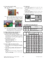
5.2.5. Green Eye Inspection Guide
Step 1. Turn on the TV set.
Step 2. Press “EYE” button on the Adjustment remote
controller.
Step 3. Block the Intelligent Sensor module on the front C/A
about 6 seconds. When the “Sensor Data” is lower
than 20, you can see the “OK” message => If it doesn’t
show “OK” message, the Sensor Module is defected
one. You have to replace that with a good one.
Step 4. After check the “OK” message come out, take out your
hand from the Sensor module. => Check “Backlight”
value change from “0” to “100” or not. If it doesn’t
change the value, the sensor is also defected one.
5.3. Manual White balance Adjustment
5.3.1. W/B adj. Objective & How-it-works
(1) Objective: To reduce each Panel’s W/B deviation
(2) How-it-works: When R/G/B gain in the OSD is at 192, it
means the panel is at its Full Dynamic Range. In order to
prevent saturation of Full Dynamic range and data, one of
R/G/B is fixed at 192, and the other two is lowered to find
the desired value.
(3) Adj. condition: normal temperature
1) Surrounding Temperature: 25 ± 5 ºC
2) Warm-up time: About 5 Min
3) Surrounding Humidity: 20% ~ 80%
4) Before White balance adjustment, Keep power on status,
don’t power off
5.3.2. Adj. condition and cautionary items
(1) Lighting condition in surrounding area surrounding lighting
should be lower 10 lux. Try to isolate adj. area into dark
surrounding.
(2) Probe location: Color Analyzer (CA-210) probe should be
within 10cm and perpendicular of the module surface
(80°~ 100°)
(3) Aging time
1) After Aging Start, Keep the Power ON status during 5
Minutes.
2) In case of LCD, Back-light on should be checked using no
signal or Full-white pattern.
5.3.3. Equipment
(1) Color Analyzer: CA-210 (NCG: CH 9 / WCG: CH12 / LED:
CH14 / OLED : CH : 17)
(2) Adj. Computer (During auto adj., RS-232C protocol is
needed)
(3) Adjust Remocon
(4) Video Signal Generator MSPG-925F 720p/204-Gray
(Model: 217, Pattern: 49)
※
Color Analyzer Matrix should be calibrated using CS-1000
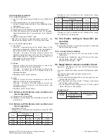
5.3.4. Equipment connection
5.3.4. Adjustment Command (Protocol)
(1) RS-232C Command used during auto-adj
RS-232C COMMAND
Explanation
CMD
DATA
ID
Wb
00
00
Begin White Balance adj.
Wb
00
ff
End White Balance adj.
(internal pattern disappears )
(2) Adjustment Map
Adj. item
Command
(lower case ASCII)
Data Range
(Hex.)
Default
(Decimal)
CMD1
CMD2
MIN
MAX
Cool
R Gain
j
g
00
C0
TBD
G Gain
j
h
00
C0
TBD
B Gain
j
i
00
C0
TBD
R Cut
TBD
G Cut
TBD
B Cut
TBD
Medium
R Gain
j
a
00
C0
TBD
G Gain
j
b
00
C0
TBD
B Gain
j
c
00
C0
TBD
R Cut
TBD
G Cut
TBD
B Cut
TBD
Warm
R Gain
j
d
00
C0
TBD
G Gain
j
e
00
C0
TBD
B Gain
j
f
00
C0
TBD
R Cut
TBD
G Cut
TBD
Color Analyzer
Computer
Pattern Generator
RS-232C
RS-232C
RS-232C
Probe
Signal Source
* If TV internal pattern is used, not needed

