background image

Copyright              LG Electronics. Inc. All right reserved. 
Only for training and service purposes

LGE Internal Use Only

C

2007

- 4 -

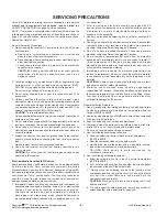
CAUTION: Before servicing receivers covered by this service
manual and its supplements and addenda, read and follow the

SAFETY PRECAUTIONS on page 3 of this publication.
NOTE:  If unforeseen circumstances create conflict between the
following servicing precautions and any of the safety precautions on
page 3 of this publication, always follow the safety precautions.
Remember: Safety First.

General Servicing Precautions
1.  Always unplug the receiver AC power cord from the AC power

source before;
a.  Removing or reinstalling any component, circuit board

module or any other receiver assembly.

b.  Disconnecting or reconnecting any receiver electrical plug or

other electrical connection.

c. Connecting a test substitute in parallel with an electrolytic

capacitor in the receiver.
CAUTION: A wrong part substitution or incorrect polarity
installation of electrolytic capacitors may result in an
explosion hazard.

2.  Test high voltage only by measuring it with an appropriate high

voltage meter or other voltage measuring device (DVM,
FETVOM, etc) equipped with a suitable high voltage probe.
Do not test high voltage by "drawing an arc".

3.  Do not spray chemicals on or near this receiver or any of its

assemblies.

4. Unless specified otherwise in this service manual, clean

electrical contacts only by applying the following mixture to the
contacts with a pipe cleaner, cotton-tipped stick or comparable
non-abrasive applicator; 10% (by volume) Acetone and 90% (by
volume) isopropyl alcohol (90%-99% strength)
CAUTION: This is a flammable mixture.
Unless specified otherwise in this service manual, lubrication of
contacts in not required.

5.  Do not defeat any plug/socket B+ voltage interlocks with which

receivers covered by this service manual might be equipped.

6.  Do not apply AC power to this instrument and/or any of its

electrical assemblies unless all solid-state device heat sinks are
correctly installed.

7.  Always connect the test receiver ground lead to the receiver

chassis ground before connecting the test receiver positive
lead.
Always remove the test receiver ground lead last.

8.  Use with this receiver only the test fixtures specified in this

service manual.
CAUTION: Do not connect the test fixture ground strap to any
heat sink in this receiver.

Electrostatically Sensitive (ES) Devices
Some semiconductor (solid-state) devices can be damaged easily
by static electricity. Such components commonly are called
Electrostatically Sensitive (ES) Devices. Examples of typical ES
devices are integrated circuits and some field-effect transistors and
semiconductor "chip" components. The following techniques
should be used to help reduce the incidence of component
damage caused by static by static electricity.
1.  Immediately before handling any semiconductor component or

semiconductor-equipped assembly, drain off any electrostatic
charge on your body by touching a known earth ground.
Alternatively, obtain and wear a commercially available
discharging wrist strap device, which should be removed to
prevent potential shock reasons prior to applying power to the

unit under test.

2.  After removing an electrical assembly equipped with ES

devices, place the assembly on a conductive surface such as
aluminum foil, to prevent electrostatic charge buildup or
exposure of the assembly.

3.  Use only a grounded-tip soldering iron to solder or unsolder ES

devices.

4. Use only an anti-static type solder removal device. Some solder

removal devices not classified as "anti-static" can generate
electrical charges sufficient to damage ES devices.

5.  Do not use freon-propelled chemicals. These can generate

electrical charges sufficient to damage ES devices.

6.  Do not remove a replacement ES device from its protective

package until immediately before you are ready to install it.
(Most replacement ES devices are packaged with leads
electrically shorted together by conductive foam, aluminum foil
or comparable conductive material).

7.  Immediately before removing the protective material from the

leads of a replacement ES device, touch the protective material
to the chassis or circuit assembly into which the device will be
installed.
CAUTION: Be sure no power is applied to the chassis or circuit,
and observe all other safety precautions.

8. Minimize bodily motions when handling unpackaged

replacement ES devices. (Otherwise harmless motion such as
the brushing together of your clothes fabric or the lifting  of your
foot from a carpeted floor can generate static electricity
sufficient to damage an ES device.)

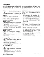
General Soldering Guidelines
1.  Use a grounded-tip, low-wattage soldering iron and appropriate

tip size and shape that will maintain tip temperature within the
range or 500

°

F to 600

°

F.

2.  Use an appropriate gauge of RMA resin-core solder composed

of 60 parts tin/40 parts lead.

3.  Keep the soldering iron tip clean and well tinned.
4.  Thoroughly clean the surfaces to be soldered. Use a mall wire-

bristle (0.5 inch, or 1.25cm) brush with a metal handle.
Do not use freon-propelled spray-on cleaners.

5.  Use the following unsoldering technique

a.  Allow the soldering iron tip to reach normal temperature.

(500

°

F to 600

°

F)

b.  Heat the component lead until the solder melts.
c.  Quickly draw the melted solder with an anti-static, suction-

type solder removal device or with solder braid.
CAUTION: Work quickly to avoid overheating the
circuitboard printed foil.

6.  Use the following soldering technique.

a.  Allow the soldering iron tip to reach a normal temperature

(500

°

F to 600

°

F)

b.  First, hold the soldering iron tip and solder the strand against

the component lead until the solder melts.

c.

Quickly move the soldering iron tip to the junction of the

component lead and the printed circuit foil, and hold it there
only until the solder flows onto and around both the
component lead and the foil.
CAUTION: Work quickly to avoid overheating the circuit
board printed foil.

d.

Closely inspect the solder area and remove any excess or

splashed solder with a small wire-bristle brush.

SERVICING PRECAUTIONS

Summary of Contents for 47LY3DF

Page 1: ...LCD TV SERVICE MANUAL CAUTION BEFORE SERVICING THE CHASSIS READ THE SAFETY PRECAUTIONS IN THIS MANUAL CHASSIS LA73A MODEL 47LY3DF 47LY3DF UA website http biz LGservice com Internal Use Only ...

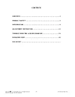
Page 2: ... All right reserved Only for training and service purposes LGE Internal Use Only C 2007 2 CONTENTS CONTENTS 2 PRODUCT SAFETY 3 SPECIFICATION 6 ADJUSTMENT INSTRUCTION 12 TROUBLE SHOOTING BLOCK DIAGRAM 16 EXPLODED VIEW 43 SVC SHEET ...

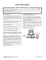
Page 3: ...afe to operate without damage of electrical shock Leakage Current Cold Check Antenna Cold Check With the instrument AC plug removed from AC source connect an electrical jumper across the two AC plug prongs Place the AC switch in the on position connect one lead of ohm meter to the AC plug prongs tied together and touch other ohm meter lead in turn to each exposed metallic parts such as antenna ter...

Page 4: ...ge on your body by touching a known earth ground Alternatively obtain and wear a commercially available discharging wrist strap device which should be removed to prevent potential shock reasons prior to applying power to the unit under test 2 After removing an electrical assembly equipped with ES devices place the assembly on a conductive surface such as aluminum foil to prevent electrostatic char...

Page 5: ... the solder joints of the two original leads If they are not shiny reheat them and if necessary apply additional solder Fuse and Conventional Resistor Removal Replacement 1 Clip each fuse or resistor lead at top of the circuit board hollow stake 2 Securely crimp the leads of replacement component around notch at stake top 3 Solder the connections CAUTION Maintain original spacing between the repla...

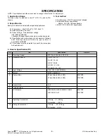
Page 6: ...470WU1 SLC1 47LY3DF 9 Operating Environment 1 Temp 0 40 deg 2 Humidity 80 10 Storage Environment 1 Temp 20 60 deg 2 Humidity 85 1 Application Range This spec sheet is applied to the 47 LCD TV used LA73A chassis 2 Especificación Each part is tested as below without special appointment 2 1 Temperature 25 5 C 77 9 F CST 40 5 C 2 2 Relative Humidity 65 10 2 3 Power Voltage Standard input voltage 100 2...

Page 7: ...ess uniformity 80 Full white 4 Color coordinate RED X 0 663 0 03 Y 0 324 0 03 GREEN X 0 194 0 03 Y 0 659 0 03 BLUE X 0 141 0 03 Y 0 082 0 03 WHITE X 0 279 0 03 Y 0 292 0 03 5 Color coordinate uniformity N A 6 Contrast ratio 3500 1 5000 1 52LB5DF UC 7 Color Temperature Cool 11 000 Test Signal Medium 9 300 HDMI input With 16 gray pattern Warm 6 500 6th bar from right 8 Color Distortion DG 10 0 9 Col...

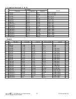
Page 8: ...1 29 97 HDTV 1080P 7 RGB PC No Resolution H freq kHz V freq Hz Pixel clock MHz Remark PC DDC 1 640 350 31 468 70 09 25 17 EGA X 2 720 400 31 469 70 08 28 32 DOS O 3 640 480 31 469 59 94 25 17 VESA VGA O 4 640 480 37 861 72 80 31 50 VESA VGA O 5 640 480 37 500 75 00 31 50 VESA VGA O 6 800 600 35 156 56 25 36 00 VESA SVGA O 7 800 600 37 879 60 31 40 00 VESA SVGA O 8 800 600 48 077 72 18 50 00 VESA S...

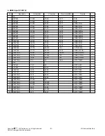
Page 9: ...0 00 65 00 VESA XGA _ 11 1024 768 56 476 70 06 75 00 VESA XGA _ 12 1024 768 60 023 75 02 78 75 VESA XGA _ 13 1280 768 47 776 59 870 79 5 CVT WXGA _ 14 1360 768 47 712 60 015 85 50 VESA WXGA _ 15 1280 1024 63 981 60 020 108 00 VESA SXGA _ 16 1280 1024 79 976 75 025 135 VESA SXGA _ 17 1600 1200 75 00 60 00 162 VESA UXGA _ 18 1920 1080 67 5 60 148 5 HDTV 1080P _ DTV 1 720 480 31 47 60 SDTV 480P 2 720...

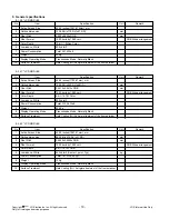
Page 10: ...1067 31mm mm 2 Outline dimension 983 0 H x576 0 V x51 0 D mm 3 Pixel Pitch 0 4845x0 4845x RGB mm 4 Pixel Format 1920 horiz by 1080 vert RGB Stripe arrangement 5 Color Depth 8 bit 16 7M Color 6 Luminance White 550 cd m2 Center 1 point Typ kg 7 Power Consumption Total 167 3 Watt Typ 8 Weight 13Kg 9 Display Operating Mode Transmissive Mode Normally Black 10 Surface Treatment Hard Coating 3H Anti glar...

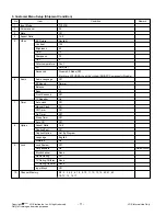
Page 11: ...3 2 Mode Off Black Level RF HDMI Low AV High RGB PC Component Disable 6 Audio Audio Language Off EZ Sound Normal Balance 0 Bass 50 Front Surround Off TV Speaker On 7 Timer Auto clock Off Manual Clock Off Off Timer Off On Timer Off Sleep Timer Off Auto Off Off 8 Option Aspect Ratio 16 9 Caption Text Off Caption Option Set By Program Language English Simplink On 9 Lock Lock System Off Set password O...

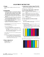
Page 12: ... the 100 FULL WHITE PATTERN In this mode you can heat run the set without separate signal generator Caution When you keep the still screen on for more than 20 minutes Especially for internal Digital pattern 13 CH Cross Hatch Pattern 09CH with higher black white contrast be careful not to create residual image on the black level part 3 Board adjustment Adjust 480i Comp1 Adjust 1080p Comp1 RGB Adjus...

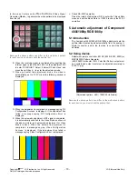
Page 13: ...al is completed it is automatically switched to the Video Mode as shown in the above picture and automatic adjustment for Video Mode is done When the automatic adjustment is completed a message saying Video Configuration Success is displayed If the adjustment has failed a message saying Video Configuration Error is displayed O Check RS 232C operation Press the Instart of adjustment R C to enter th...

Page 14: ... adjustment for component 1 first I When the adjustment is normally completed a message saying ADC Component1 Success is displayed and when the adjustment is not normally completed a message saying ADC Component1 1080P Fail is displayed J After the Component1 adjustment is completed it is automatically switch to RGB DTV Mode to start RGB adjustment When the adjustment is normally completed a messa...

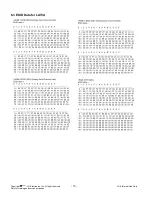
Page 15: ...Copyright LG Electronics Inc All right reserved Only for training and service purposes LGE Internal Use Only C 2007 15 6 3 EDID Data for LA73A ...

Page 16: ... chassis from the adjuster Caution For automatic adjustment RS 232C Command and Chassis are commonly applied 7 3 1 White Balance adjustment For automatic adjustment Execute Power Only Key of the adjustment R C to execute automatic adjustment Set the Baud Rate to 115200 Always start adjustment with wb 00 00 and end adjustment with wb 00 ff Adjust the offset if necessary 7 4 White Balance adjustment...

Page 17: ...caler 1 or 2 Alive IC when Standby Alive IC when Standby Audio Video TP AV2 L R MNT Out L R COMP1 L R COMP2 L R RGB L R TP_IN1 AV1 AV2 AV1 Y C1 AV2 Y C2 Flash NOR 32MB Flash NOR 32MB Latch x 2 Latch x 2 24C512 24C512 Cable AT NT VSB LGDT3303 VSB LGDT3303 63LVD1023 63LVD1023 1080P LVDS Con 1080P LVDS Con Dual AV1 L R GPIO I2S ATI X260 of MPEG decoder COMP2 RGB CS8416 CS8416 HDMI SPDIF I2S I2S MST33...

Page 18: ...Tuner 0xC2 HDMI ADC MST3361 0X9C Temp Sensor LM75 0X94 U Com MTV416 0x50 I2C_CH1 3 3V_L 5V_L I2C_CH2 3 3V_L 5V_L I2C_CH3 3 3V_L Port Expander M62320 0X74 Audio Switch MSP4450K 0X80 DASP NTP3000 0X54 PDP Module 0x1C VSB QAM LGDT3703 Main 0X1C Live Dead CS8416A 0X20 W 0X21 R EEPROM 24LC512 0xA6 CH1 CH2 CH3 FRC94XYH 0xD4 EEPROM 24LC16 5V 5V 5V 2 5V ...

Page 19: ...B ISL6549CB 1 2V 1 8V ISL6549CB ISL6549CB 1 8V MK3727D MK3727D 74LVT16373 2EA 74LVT16373 2EA S29GL256 S29GL256 THC63LVD1023 THC63LVD1023 3 3V_L HYB18T512 4EA HYB18T512 4EA MK3727D MK3727D 19 0V 19 0V NTP3000 NTP3000 NTP3000 NTP3000 1 8V BA033FP 3 3 BA033FP 3 3 MTV416 MTV416 AZ1086 1 8 AZ1086 1 8 AZ1117H 3 3 AZ1117H 3 3 SC1565 2 5 SC1565 2 5 MST3369 MST3369 9 0V TEA6420 TEA6420 9 0V CS8416 CS8416 K...

Page 20: ...ive IC when Standby Alive IC when Standby Audio Video TP AV2 L R MNT Out L R COMP1 L R COMP2 L R RGB L R TP_IN1 AV1 AV2 AV1 Y C1 AV2 Y C2 Flash NOR 32MB Flash NOR 32MB Latch x 2 Latch x 2 24C512 24C512 Cable AT NT VSB LGDT3303 VSB LGDT3303 63LVD1023 63LVD1023 1080P LVDS Con 1080P LVDS Con Dual AV1 L R GPIO I2S ATI X260 of MPEG decoder COMP2 RGB CS8416 CS8416 HDMI SPDIF I2S I2S MST3361 1HDMI 1ADC M...

Page 21: ...Check P600 47 DISP_EN 33 TXAC 32 TXAC 17 TXBC 16 TXBC Check THC63LVD1023 IC601 Check LVDS Cable Check PDP LCD Module Control board 1 2 3 4 5 1 _Check the L729 HIGH _Check Power connector Y N Y Y Y Y Y N N 2 _Check the THC63LVD1023 IC601 input signal Clk 74 25MHz 3 _Check the P600 input signal 47 DISP_EN 33 TXAC 74 25MHz 3 3V GND 32 TXAC 4 _Check the LVDS Cable 5 _Check the PDP Module control board...

Page 22: ...ng and service purposes LGE Internal Use Only C 2007 22 EXT 1 2 X260 TP A Comp1 2 RGB CVBS TP C TP B 656 AT NT TUNER LGDT 3303 VSB1 QAM TP MST 3361 HS VS DVI HS VS YCbCr2 YCbCr or RGB FRC9445H RGB CVBS YCbCr1 DVO Y C1 Y C2 Y C1 Y C2 AV1 2 AV1 2 HDMI 1 2 3 TMDS341A ...

Page 23: ...nc All right reserved Only for training and service purposes LGE Internal Use Only C 2007 23 Check Antenna Cable Check Tuner 5V Video out Check X260 inputs M_TU_CVBS C2117 Check CVBS Video Path 1 _Check Tuners Vcc and Video out ...

Page 24: ...ng and service purposes LGE Internal Use Only C 2007 24 EXT 1 2 X260 TP A Comp1 2 RGB CVBS TP C TP B 656 AT NT TUNER LGDT 3303 VSB1 QAM TP MST 3361 HS VS DVI HS VS YCbCr2 YCbCr or RGB FRC9445H RGB CVBS YCbCr1 DVO Y C1 Y C2 Y C1 Y C2 AV1 2 AV1 2 HDMI 1 2 3 TMDS341A ...

Page 25: ...and service purposes LGE Internal Use Only C 2007 25 Check Antenna Cable Check Tuner TU600 5V IF out Check LGDT3303 IC604 inputs power pins Osc 25Mhz IF pin Check LGDT3303 Outputs 3 _ Check X260 Input CLK SOP Valid Error Data Check X260 INPUT CLK SOP Valid Error Data ...

Page 26: ...ng and service purposes LGE Internal Use Only C 2007 26 EXT 1 2 X260 TP A Comp1 2 RGB CVBS TP C TP B 656 AT NT TUNER LGDT 3303 VSB1 QAM TP MST 3367 HS VS DVI HS VS YCbCr2 YCbCr or RGB FRC9445H RGB CVBS YCbCr1 DVO Y C1 Y C2 Y C1 Y C2 AV1 2 AV1 2 HDMI 1 2 3 TMDS341A ...

Page 27: ...Check Signal format supported format Check STMAV335 IC403 Power Pins Comp1 2 5 11 Comp2 3 6 10 RGB 9 4 7 RGB_V H R400 R401 Check STMAV335 IC403 outputs 14 MUX_OUT_Y 13 MUX_OUT_Pb 8 MUX_OUT_Pr Check MST3361 IC402 OSC Power pins 44 Y_in 41 Cb_in 46 Cr_in 37 H 38 V 1 2 3 Check MST3361 IC402 Outputs V out 99 H out 98 Clock 96 Data 30Bit DE 97 Check X260 IC101 Inputs MST3361_HS T6 MST3361_VS T5 Clock P...

Page 28: ...ng and service purposes LGE Internal Use Only C 2007 28 EXT 1 2 X260 TP A Comp1 2 RGB HDMI 1 2 3 CVBS TP C TP B 656 AT NT TUNER LGDT 3303 VSB1 QAM TP MST 3367 HS VS DVI HS VS YCbCr2 YCbCr or RGB FRC9445H RGB CVBS YCbCr1 DVO Y C1 Y C2 Y C1 Y C2 AV1 2 AV1 2 TMDS341A ...

Page 29: ...361 IC402 inputs RX1C RX1C Vsync DE Clk Hsync 59 94Hz Frequency Different according to format Data 5 _Check X260 IC101 Inputs _Signal shape is same above Snow noise White dot Power off and on TV or STB DVD Video is normal No Sound Check HDCP Power Pin IC404 MST3361 IC402 IIC 69 70 Check MST3361 IC402 inputs Power Osc 25 26 RX1C RX1C 14 15 RX0C RX0C Re download EDID IC406 407 408 Check MST3361 IC40...

Page 30: ...GMF IC309 and Re download Check SI3865 Q702 2 3pin 5V Normal Replace Power board Normal Check P702 all input voltage Normal YES Check SI3865 Q1901 Q1902 Q1903 2 3pin 3 3V Normal YES Check SI3865 Q702 5pin 3 3V Normal Check SI3865 Q1901 Q1902 Q1903 5pin 3 3V Normal NO NO NO Check P702 wafers connectors Normal YES Check P701 3 8Pin 5V Normal YES Replace power board NO NO Replace SI3865 Q702 YES Repl...

Page 31: ...load Check SI3865 Q702 2 3pin 5V Normal Check SI3865 Q1901 Q1902 Q1903 2 3pin 3 3V Normal YES Check SI3865 Q702 5pin 3 3V Normal Check SI3865 Q1901 Q1902 Q1903 5pin 3 3V Normal NO NO Replace SI3865 Q702 YES Replace SI3865 Q1901 Q1902 Q1903 YES NO YES Check SI4800 Q315 1 2 3Pin 1 9V Normal Replace SI4800 Q315 Replace SC2621 IC304 YES NO NO Check between FB1714 and C345 1 2V Normal Replace SI4800 Q3...

Page 32: ...Use Only C 2007 32 EXT1 2 AT NT TUNER LGDT 3303 X260 TP A HDMI 1 2 3 TP C RGB COMP 1 2 SIF SIF IN 1 NTP 3000 SIF IN 2 I2S IN 1 I2S IN 2 I2S OUT 1 SPDIF Ø CS8416 I2S I2S I2S I2S S PDIF SPDIF L R L R L R L R ANT Cable VSB TP MSP4450K MNT OUT I2S I2S I2SI 3 I2SO 1 SC 2 MCLK MCLK SPDIF OUT Optical Coaxial ...

Page 33: ... Left R5063 Right 1 2 3 4 If DTV or HDMI input Check X260 IC101 Output R153 SCLK R154 LRCLK R155 DATA Check MSP4450K IC508 Input R5059 SCLK R5060 LRCLK R5061 DATA Check MNT Output Jack J704 Monitor L R Out Check MSP4450K IC508 Power 5 Check MSP4450K IC508 X tal Input X tal Input 71 72pin 18 432MHz 6 If ATV AV Component RGB input Check MSP4450K IC508 Input C5016 ATV_SIF R5041 AV1_R R5042 AV1_L R504...

Page 34: ...7 34 AT NT TUNER LGDT 3303 X260 TP A HDMI 1 2 3 TP C SIF SIF IN 1 NTP 3000 SIF IN 2 I2S IN 1 I2S IN 2 I2S OUT 1 SPDIF Ø CS8416 I2S I2S I2S I2S S PDIF SPDIF ANT Cable VSB TP MSP4450K I2S I2S I2SI 3 I2SO 1 MCLK MCLK SPDIF OUT Optical Coaxial EXT1 2 RGB COMP 1 2 SIF L R L R L R L R MSP4450K MNT OUT I2SI 3 I2SO 1 SC 2 ...

Page 35: ...IF lines C6025 C6026 Check MSP4450K IC508 inputs C5016 67pin 1 2 3 4 5 6 Follow the procedure of COMMON SOUND OUT 7 8 Check Tuner TU600 5V 3 5 9 17 pin SIF 18 pin Check Antenna Cable Check X260 IC101 Intputs R175 SCLK R176 LRCLK R177 DATA Check MSP4450K IC508 Power Check MSP4450K IC508 outputs R5039 SCLK R5040 LRCLK R5043 DATA ...

Page 36: ...Use Only C 2007 36 EXT1 2 AT NT TUNER LGDT 3303 X260 TP A HDMI 1 2 3 TP C RGB COMP 1 2 SIF SIF IN 1 NTP 3000 SIF IN 2 I2S IN 1 I2S IN 2 I2S OUT 1 SPDIF Ø CS8416 I2S I2S I2S I2S S PDIF SPDIF L R L R L R L R ANT Cable VSB TP MSP4450K MNT OUT I2S I2S I2SI 3 I2SO 1 SC 2 MCLK MCLK SPDIF OUT Optical Coaxial ...

Page 37: ...ly C 2007 37 Check LGDT3303 IC604 inputs IF_N 8 pin C645 IF_P 7 pin C644 Check LGDT3303 IC604 outputs VSB DATA AR651 AR656 VSB_CLK R658 VSB ERROR VALID SOP AR657 1 2 3 4 5 6 Follow the procedure of COMMON SOUND OUT Check Tuner TU600 5V 3 5 9 17 pin IF_N 15 pin IF_P 14pin Check Antenna Cable Check X260 IC101 ...

Page 38: ...Use Only C 2007 38 EXT1 2 AT NT TUNER LGDT 3303 X260 TP A TP C RGB COMP 1 2 SIF SIF IN 1 NTP 3000 SIF IN 2 I2S IN 1 I2S IN 2 I2S OUT 1 SPDIF Ø CS8416 I2S I2S I2S I2S S PDIF SPDIF L R L R L R L R ANT Cable VSB TP MSP4450K MNT OUT I2S I2S I2SI 3 I2SO 1 SC 2 MCLK MCLK SPDIF OUT Optical Coaxial HDMI 1 2 3 ...

Page 39: ...3 DATA 1 2 3 5 6 7 Follow the procedure of COMMON SOUND OUT Check MSP4450K IC508 Inputs R5041 AV1_R 5042 AV1_L R5045 AV2_R R5046 AV2_L R5048 CMP1_R R5049 CMP1_L R5051 CMP2_R 5052 CMP2_L R5055 RGB_R R5058 RGB_L Check AV COMPONENT RGB Cable Check X260 IC101 Inputs R175 SCLK R176 LRCLK R177 DATA Check MSP4450K IC508 X tal Input X tal Input 71 72pin Check MSP4450K IC508 Power 4 ...

Page 40: ...Use Only C 2007 40 EXT1 2 AT NT TUNER LGDT 3303 X260 TP A TP C RGB COMP 1 2 SIF SIF IN 1 NTP 3000 SIF IN 2 I2S IN 1 I2S IN 2 I2S OUT 1 SPDIF Ø CS8416 I2S I2S I2S I2S S PDIF SPDIF L R L R L R L R ANT Cable VSB TP MSP4450K MNT OUT I2S I2S I2SI 3 I2SO 1 SC 2 MCLK MCLK SPDIF OUT Optical Coaxial HDMI 1 2 3 ...

Page 41: ... Internal Use Only C 2007 41 Check CS8416 IC501 inputs HDMI_SPDIF C5005 1 2 3 4 5 Follow the procedure of COMMON SOUND OUT 6 Check MST3361 IC402 output HDMI_SPDIF R409 Check HDMI Cable Check X260 IC101 Inputs SCLK R175 LRCLK R176 DATA R177 Check CS8416 IC501 outputs DATA 26 SCLK 27 LRCLK 28 ...

Page 42: ...power adaptor Check VBUS_5V Check the DC DC Converter IC712 N Y Y N N 2 Check Sequence Replace the cable to USB1 1 cable or Replace the device Y N Replace the DC DC Converter IC712 Exception USB power could be disabled by inrushing current In this case remove the device and try to reboot the TV AC power off on X260 USB_ link IC101 DC DC Converter IC712 J A C K Side B D USB1 1_OVRCUR 5V_USB VBUS_5V...

Page 43: ...cs Inc All right reserved Only for training and service purposes LGE Internal Use Only C 2007 43 EXPLODED VIEW 300 121 120 800 500 510 800 700 520 200 200T 812 813 810 811 814 815 816 530 817 900 910 610 600 830 820 400 200N ...

Page 44: ......

Page 45: ......

Page 46: ...Oct 2007 Printed in Korea P NO MFL35929317 ...

Reviews: