ADJUSTMENT INSTRUCTION
- 10 -
LGE Internal Use Only
Copyright LG Electronics. Inc. All right reserved.
Only for training and service purposes
1. Application
This spec sheet is applied all of the Digital Signage Product
with LWB1A chassis.
Ex. ) LW01A :47WV30
2. Designation
1) The adjustment is according to the order which is
designated and which must be followed, according to the
plan which can be changed only on agreeing.
2) Power Adjustment: Free Voltage
3) Magnetic Field Condition: Nil.
4) Input signal Unit: Product Specification Standard
5) Reserve after operation: Above 5 Minutes (Heat Run)
Temperature : at 25 °C ± 5 °C
Relative humidity : 65 % ± 10 %
Input voltage : 220 V, 60 Hz
6) Color Analyzer (CA-210 or CA-110), DDC Adjustment Jig
equipment, SVC remote controller.
7) Push The “IN STOP KEY” - For memory initialization.
Case1 : Software version up
1. After downloading S/W by USB , Multi-vision set will
reboot automatically
2. Push “In-stop” key
3. Push “Power on” key
4. Function inspection
5. After function inspection, Push “In-stop” key.
Case2 : Function check at the assembly line
1. When TV set is entering on the assembly line, Push
“In-stop” key at first.
2. Push “Power on” key for turning it on.
--> If you push “Power on” key, TV set will recover
channel information by itself.
3. After function inspection, Push “In-stop” key.
3. Main PCB check process
3.1. ADC Process
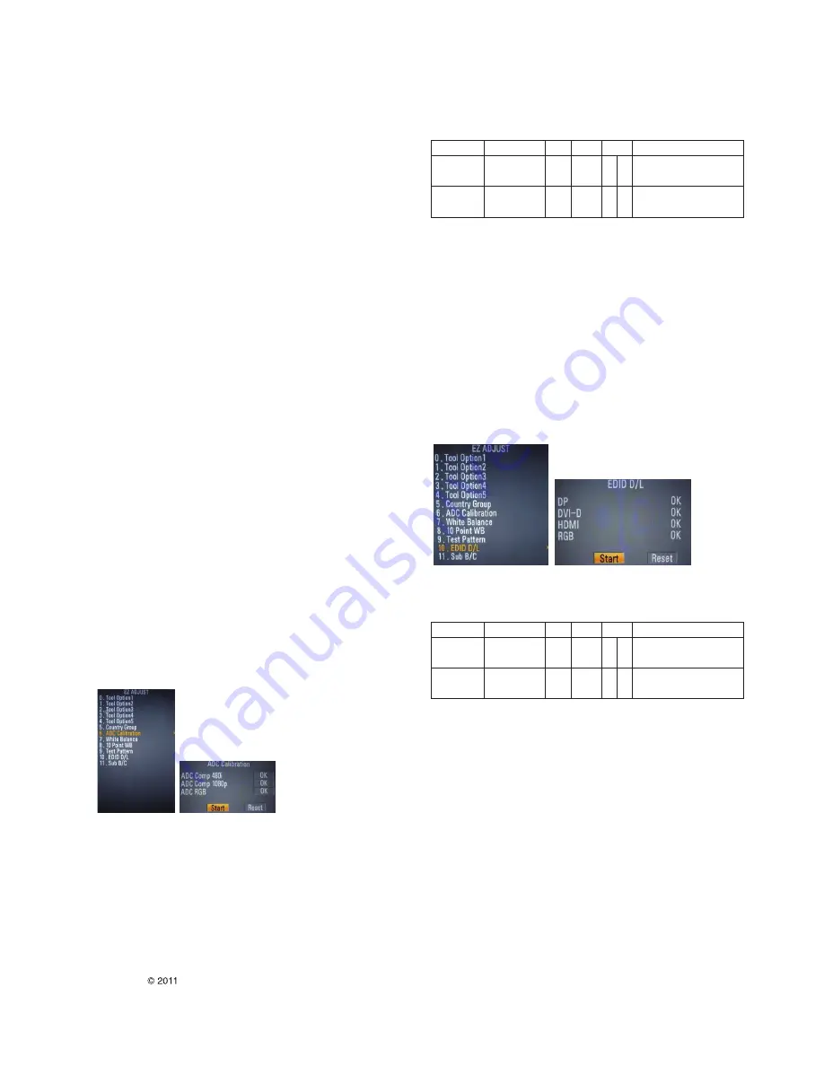
3.1.1 ADC
· Enter Service Mode by pushing “ADJ” key,
· Enter Internal ADC mode by pushing “
G
” key at “ADC
Calibration”
--> Caution: Using ‘power on’ button of the Adjustment R/C ,
power on Multi-vision.
* ADC Calibration Protocol (RS232)
Adjust Sequence
*aa 00 00 [Enter Adjust Mode]
*xb 00 40 [Component1 Input (480i)]
*ad 00 10 [Adjust 480i Comp1]
*xb 00 60 [RGB Input (1024*768)]
*ad 00 10 [Adjust 1024*768 RGB]
*aa 00 90 End Adjust mode
*Required equipment : Adjustment R/C.
3.2. DDC EDID Download
- Auto Download
· After enter Service Mode by pushing “ADJ” key,
· Enter EDID D/L mode.
· Enter “START” by pushing “OK” key.
--> Caution: Never connect HDMI & D-sub Cable when EDID
downloaded.
* Edid data and Model option download (RS232)
3.2.1. DDC EDID Write (RGB 128Byte )
· Connect D-sub Signal Cable to D-Sub Jack.
· Write EDID DATA to EEPROM (24C02) by using DDC2B
protocol.
· Check whether written EDID data is correct or not.
* For SVC main Ass’y, EDID have to be downloaded to Insert
Process in advance.
NO.
Item
CMD 1 CMD 2
Data 0
Enter
Adjust ‘Mode In’
A
A
0 0
When transfer the ‘Mode In’
Adjust MODE
Carry the command.
ADC adjust
ADC Adjust
A
D
1 0
Automatically adjustment
(The use of a internal pattern)
NO.
Item
CMD 1 CMD 2
Data 0
Enter
Download
A
A
0 0
When transfer the ‘Mode In’
download MODE
‘Mode In’
Carry the command.
EDID data and
Download
A
E
00 10
Automatically adjustment
Model option
(The use of a internal pattern)
Summary of Contents for 42WS10
Page 31: ......


