- 14 -
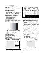
8. Auto Component Color Balance
8-1. Required Test Equipment
1) Remote controller for adjustment
2) 802F Pattern Generator
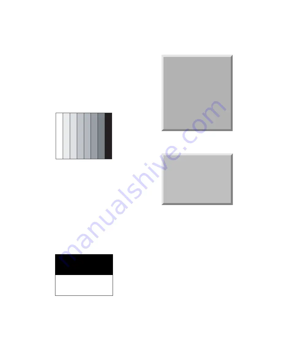
(Which has 720p Ypbpr output & PC 1024x768 60Hz with
Standard(0.7Vpp) Vertical 100% Color Bar Pattern as Fig.8)
8-2. Method of Auto Component Color Balance
1) Input the Component 720p 100% Color Bar signal into
Component1 or Component2.
2) Set the PSM to Standard mode in Picture menu.
3) Press INSTART key on R/C for adjustment.
4) Press the
G
(Vol. +) key operate To set, then it becomes
automatically.
5) Auto-RGB OK means complete adjustment
9. Auto RGB Color Balance
9-1. Required Test Equipment
1) Remote controller for adjustment
2) 802F Pattern Generator, Master (MSPG-925FA), etc.
(Which has XGA 60Hz PC Format output with standard
(0.7Vpp) horizontal black and white pattern as Fig.10)
9-2. Method of Auto RGB Color Balance
1) Input the PC 1024x768 60Hz horizontal black and white
pattern into RGB.
2) Set the PSM to Standard mode in Picture menu.
3) Press ADJ key on R/C for adjustment.
4) Press the
G
(Vol. +) key operate To set, then it becomes
automatically.
5) Auto-RGB OK means completed adjustment.
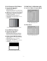
9. Default Value in Adjustment mode
9-1. Auto Color Balance (Component/RGB)
9-2. White Balance
Level : 0
Level : 255
(Fig. 9) Auto RGB Color Balance Test Pattern
(Fig. 10) Default Value on OSD
(Fig. 10-1) Default Value on OSD
Auto Color Balance(HEX)
Auto-RGB
)
G
To Set
Red
)
Offset1
))
80
Green
)
Offset1
))
80
Blue
)
Offset1
))
80
Red
)
Offset2
))
80
Green
)
Offset2
))
80
Blue
)
Offset2
))
80
Red
)
Gain
))
80
Green
)
Gain
))
80
Blue
)
Gain
))
80
Reset
))
G
To Set
White Balance(Hex)
Red
)
Gain
))
80
Red
)
Offset
))
80
Green
)
Gain
))
80
Green
)
Offset
))
80
Blue
)
Gain
))
80
Blue
)
Offset
))
80
Reset
))
G
To Set
(Fig. 8) Auto Component Color Balance Test Pattern
Summary of Contents for 42PX3RV
Page 24: ... 24 BLOCK DIAGRAM cable ...
Page 25: ...MEMO 25 ...
Page 33: ......
Page 34: ......
Page 35: ......
Page 36: ...PRINTED CIRCUIT BOARD MAIN TOP MAIN BOTTOM SIDE A V BOTTOM CONTROL ...


