background image

24

ENG

ENGLISH

MAKING CONNECTIONS

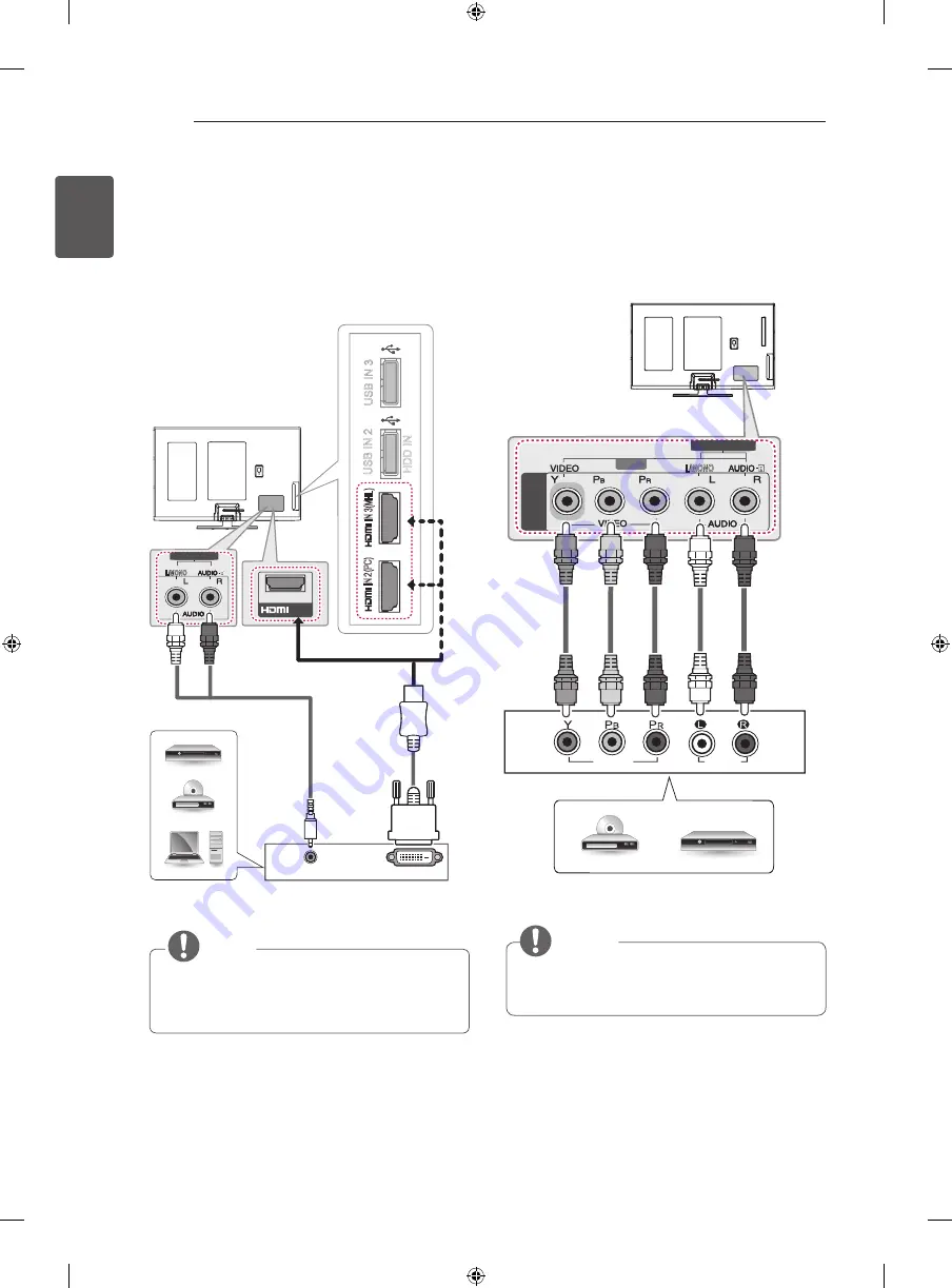
Component Connection

Transmits analog video and audio signals from an exter-

nal device to the TV. Connect the external device and the 

TV with a component cable as shown.

         NOTE


y

If cables are not installed correctly, it could cause 

this image to display in black and white or with 

distorted colours. 


AV IN 

L/MONO

COMPONENT

IN

VIDEO

AUDIO

AUDIO IN (PC)

    DVD / Blu-Ray / HD Cable Box

GREEN

GREEN

BLUE

BLUE

RED

RED

WHITE

WHITE

RED

RED

(*Not Provided)

dvI to HdMI connection

Transmits the digital video signal from an external device 

to the TV. Connect the external device and the TV with 

the DVI-HDMI cable as shown. To transmit an audio 

signal, connect an audio cable.

Choose any HDMI input port to connect. It does

not matter which port you use.


          NOTE


y

Depending on the graphics card, DOS mode may 

not work if a HDMI to DVI Cable is in use.


y

When using the HDMI/DVI cable, Single link is 

only supported

L/MONO

AUDIO IN (PC)

AUDIO OUT

1

IN (ARC)

IN 

2(P

C)

IN 3(MHL)

USB IN 

2

USB IN 

3

USB IN 

2

USB IN 

3

HDD IN

DVI OUT

(*Not Provided)

(*Not Provided)

    DVD / Blu-Ray / 

HD Cable Box / PC

WHITE

RED

Summary of Contents for 42PH4700-TD

Page 1: ...OWNER S MANUAL PLASMA TV Please read this manual carefully before operating your set and retain it for future reference PH47 PH67 P NO MFL67684602 1302 REV00 Printed in Korea www lg com ...

Page 2: ...23 HDMI Connection 24 DVI to HDMI connection 24 Component Connection 25 Composite Connection 25 MHL Connection 26 Audio Connection 26 Digital optical audio connection 26 USB Connection 27 REMOTE CONTROL 28 Magic Remote Control Functions 29 Registering Magic Remote Control 29 How to use Magic Remote Control 29 Precautions to Take when Using the Magic Remote Control 30 Pentouch 30 Pentouch Functions...

Page 3: ...t with Grounded earth pin Except for devices which are not grounded on earth Otherwise possibility you may be electrocuted or injured y y Insert power cable plug completely into wall socket otherwise if not secured completely into socket fire ignition may break out y y Ensure the power cord does not come into contact with hot objects such as a heater This may cause a fire or an electric shock haza...

Page 4: ...drop metallic objects such as coins hair pins chopsticks or wire into the product or inflammable objects such as paper and matches Children must pay particular attention Electrical shock fire or injury can occur If a foreign object is dropped into the product unplug the power cord and contact the service centre y y Do not spray water on the product or scrub with an inflammable substance thinner or...

Page 5: ...g or splashing and no objects filled with liquids such as vases shall be placed on the apparatus y y When installing the antenna consult with a qualified service technician If not installed by a qualified technician this may create a fire hazard or an electric shock hazard y y We recommend that you maintain a distance of at least 2 to 7 times the diagonal screen size when watching TV If you watch ...

Page 6: ...ing or unpacking the product work in pairs because the product is heavy Otherwise this may result in injury y y Please follow the installation instructions below to prevent the product from overheating The distance between the product and the wall should be more than 10 cm Do not install the product in a place with no ventilation e g on a bookshelf or in a cupboard Do not install the product on a ...

Page 7: ...t right top down This phenomenon occurs due to the characteristic of the panel It is not related with the product performance and it is not malfunction y y Displaying a still image e g broadcasting channel logo on screen menu scene from a video game for a prolonged time may cause damage to the screen resulting in retention of the image which is known as image sticking The warranty does not cover t...

Page 8: ...stereo blindness or stereo anomaly Double images or discomfort in viewing may be experienced y y If you have strabismus cross eyed amblyopia weak eyesight or astigmatism you may have trouble sensing depth and easily feel fatigue due to double images It is advised to take frequent breaks than the average adult y y If your eyesight varies between your right and left eye revise your eyesight prior to...

Page 9: ...tivity due to stimulation from light in 3D contents Advise them to refrain from watching 3D contens for a long time when they are tired y y Elderly The elderly may perceive less 3D effect compared to the young Do not sit closer to the TV than the recommended distance Cautions when using the 3D glasses Make sure to use LG 3D glasses Otherwise you may not be able to view 3D videos properly Do not us...

Page 10: ...ection is available You can use the TV network functions only when the network connection is made ASSEMBLING AND PREPARING Unpacking Check your product box for the following items If there are any missing accessories contact the local dealer where you purchased your product The illustrations in this manual may differ from the actual product and item CAUTION y y Do not use any unapproved items to e...

Page 11: ...r assembly 7 EA M4 x 14 Only 42PH47 See p 17 Screw for assembly 7 EA M5 x 16 Only 50PH47 50 60PH67 See p 17 Stand Body Stand Base See p 17 Isolator Depending on model See p 13 3D Glasses Depending on model Wired touch pen Only PH671 See p 30 Wired touch pen holder Only PH671 See p 30 Wired touch pen stand Only PH671 See p 30 Tip Only PH671 See p 30 Eye bolt Wall bracket Only PH671 See p 20 ...

Page 12: ...able AV cable on the ferrite core once Place the ferrite core close to the TV to an External device Figure 2 1 to the TV 10 mm 5 mm Wind the PC audio cable on the ferrite core once 3 Use the ferrite core to reduce the electromagnetic interference in the LAN cable Wind the LAN cable thrice on the ferrite core Place the ferrite core close to the TV and an External device A Gray B Gray Cross Section ...

Page 13: ...ter installation Before starting be sure that the TV antenna is connected ANTENNA CABLE IN Cable Antenna Wall Isolator 1 Connect to TV 2 Connect to Set Top box Connect one end of the isolator to cable antenna jack and the other to TV set or set top box Equipment connected to the protective earthing of the building installation through the mains connection or through other equipment with a connecti...

Page 14: ...00 Touch Pen Cradle AN TD200 Touch Pen Dongle AN VC Video call camera NOTE With the Touch Pen you can use the TV as a touch monitor with or without connectiong it to your PC You need to purchase the Touch Pen including the cradle together with the dongle Compatibility PH47 PH67 AG S3 3D Glasses AN WF100 Wireless LAN AN MR400 Magic Remote AN TP300 Touch Pen Cradle AN TD200 Touch Pen Dongle AN VC Vi...

Page 15: ...Button Description Turns the power on or off Selects the highlighted menu option or confirms an input S Accesses the main menus or saves your input and exits the menus Changes the input source H Adjusts the volume level H Scrolls through the saved programmes Buttons Screen Remote control sensor Power indicator C ...

Page 16: ... all cables y y When holding the TV the screen should face away from you to avoid damage y y Hold the top and bottom of the TV frame firmly Make sure not to hold the transparent part speaker or speaker grill area y y When transporting the TV do not expose the TV to jolts or excessive vibration y y When transporting the TV keep the TV upright never turn the TV on its side or tilt towards the left o...

Page 17: ...PARING Setting up the TV Image shown may differ from your TV Attaching the stand 3 EA M5 x 16 1 2 3 Only 50PH47 50 60PH67 Front Stand Base Stand Body Only 42PH47 3 EA M4 x 14 4 EA M5 x 16 Only 50PH47 50 60PH67 Only 42PH47 4 EA M4 x 14 ...

Page 18: ...e stand Only 50PH47 50PH67 M5 x 16 4 EA 1 1 2 2 Protection cover M5 x 16 1 EA CAUTION y y When attaching the stand to the TV set place the screen facing down on a cushioned table or flat surface to protect the screen from scratches y y Make sure that the screws are inserted correctly and fastened securely If they are not fastened securely enough the TV may tilt forward after being installed Do not...

Page 19: ...en insert and tighten the supplied screw on the rear of the stand Only 42PH47 WARNING y y To prevent TV from falling over the TV should be securely attached to the floor wall per installation instructions Tipping shaking or rocking the TV may cause injury 10 cm 10 cm 10 cm 10 cm Adjusting the angle of the TV to suit view This feature is not available for all models Swivel 20 degrees to the left or...

Page 20: ...nting on a wall Attach an optional wall mount bracket at the rear of the TV carefully and install the wall mount bracket on a solid wall perpendicular to the floor When you attach the TV to other building materials please contact qualified personnel LG recommends that wall mounting be performed by a qualified professional installer 10 cm 10 cm 10 cm 10 cm WARNING y y If a television is not positio...

Page 21: ...this may cause damage to the TV and void your warranty y y Use the screws and wall mounts that meet the VESA standard Any damages or injuries by misuse or using an improper accessory are not covered by the manufacturer s warranty NOTE y y Use the screws that are listed on the VESA standard screw specifications y y The wall mount kit includes an installation manual and necessary parts y y The wall ...

Page 22: ...Refer to the external equipment s manual for operating instructions y y If you connect a gaming device to the TV use the cable supplied with the gaming device y y In PC mode there may be noise associated with the resolution vertical pattern contrast or brightness If noise is present change the PC output to another resolution change the refresh rate to another rate or adjust the brightness and cont...

Page 23: ... Control function y y High Speed HDMI Cables are tested to carry an HD signal up to 1080p and higher y y Supported HDMI Audio format Dolby Digital DTS PCM Up to 192 KHz 32k 44 1k 48k 88k 96 k 176k 192k 1 IN ARC IN 2 PC IN 3 MHL USB IN 2 USB IN 3 USB IN 2 USB IN 3 HDMI HDD IN ARC Audio Return Channel y y An external audio device that supports SIMPLINK and ARC must be connected using HDMI IN ARC 1 p...

Page 24: ...HITE RED RED Not Provided DVI to HDMI connection Transmits the digital video signal from an external device to the TV Connect the external device and the TV with the DVI HDMI cable as shown To transmit an audio signal connect an audio cable Choose any HDMI input port to connect It does not matter which port you use NOTE y y Depending on the graphics card DOS mode may not work if a HDMI to DVI Cabl...

Page 25: ...gh definition Link MHL is an interface for transmitting digital audiovisual signals from mobile phones to television sets IN 2 PC PC IN 3 MHL USB IN 2 HDD IN USB IN 3 NOTE y y Connect the mobile phone to the HDMI IN 3 MHL port to view the phone screen on the TV y y The MHL passive cable is needed to connect the TV and a mobile phone y y This only works for the MHL enabled phone y y Some applicatio...

Page 26: ...put port Looking at the laser beam may damage your vision y y Audio with ACP Audio Copy Protection function may block digital audio output Audio Connection You may use an optional external audio system instead of the built in speaker USB Connection Connect a USB storage device such as a USB flash memory external hard drive or a USB memory card reader to the TV and access the Smart Share menu to us...

Page 27: ...saved programmes or channels PAGE Moves to the previous or next screen INFO Views the information of the current programme and screen SMART Accesses the Smart Home menus MY APPS Shows the list of Apps Navigation buttons up down left right Scrolls through menus or options OK Selects menus or options and confirms your input BACK Returns to the previous level GUIDE Shows programme guide EXIT Clears o...

Page 28: ... Control works as a regular remote control To display the pointer again shake the Magic Remote Control from side to side POWER Turns the TV on or off BACK Returns to the previous level Navigation buttons up down left right Scrolls through menus or options Pointer RF transmitter SMART Accesses the Smart Home menu Voice recognition Depending on model Adjusts the volume level ꕌPꕍ Scrolls through the ...

Page 29: ...at your TV then move it left right up or down If the pointer does not work properly leave the remote control for 10 seconds then use it again Precautions to Take when Using the Magic Remote Control y y Use the Magic Remote Control within the maximum communication distance 10 m Using the Magic Remote Control beyond this distance or with an object obstructing it may cause a communication failure y y...

Page 30: ...Description Power button Turns the wired touch pen on and off Tip Write letters and draw pictures by pressing the tip Connection cable for wired touch pen Connects the wired touch pen to the TV What is the Pentouch Function Wired Touch Pen Part Names and Components Tip Wired touch pen stand Wired touch pen holder Wired touch pen Components Only PH671 Pentouch NOTE If you purchase the wireless touc...

Page 31: ...ructions below to connect the wired touch pen to the TV 1 Connect the wired touch pen to the USB IN1 input wired pen port on the TV 2 Once the wired touch pen is connected hold the remaining wire in place using the wired touch pen holder ODQ PB PR Y DY LQ DXGLR LQ SF USB IN 4 LQ DUF L MONO COMPONENT IN ANTENNA CABLE IN ꔈ The wired touch pen must be connected to the designated USB port on the back ...

Page 32: ...onal injury Do not keep the wired touch pen in an unstable place or within the reach of children Do not allow children or pets to bite or suck the wired touch pen If the wired touch pen is treated as a toy or swallowed it may cause severe injury Do not use the wired touch pen with wet hands Do not allow foreign substances such as drinks or water to get into the wired touch pen If any foreign subst...

Page 33: ... of the product ꔈ ꔈ Do not pull the wired touch pen cable with excessive force Doing so may lengthen the cable ꔈ ꔈ Fix the wired touch pen cable using the wired touch pen holder when using the pen If the cable is not fixed on the wired touch pen holder it may damage the USB port ꔈ ꔈ Do not use the wired touch pen by connecting it to a USB extension cable or USB hub The wired touch pen may not work...

Page 34: ...ption of the function you want from the index 5 Provides the detailed information on the functions of LG Smart TV when the Internet is connected It may not be available depending on the country language Using the User guide User Guide allows you to more easily access the detailed TV information OPTION To set language SMART Settings OPTION Language Selects Menu Language and Audio Language displayed...

Page 35: ...product y y Do not spray liquid onto the surface If water enters the TV it may result in fire electric shock or malfunction Power cord Remove the accumulated dust or dirt on the power cord regularly TROUBLESHOOTING Problem Solution Cannot control the TV with the remote control y y Check the remote control sensor on the product and try again y y Check if there is any obstacle between the product an...

Page 36: ... product 5 This product does not contain any of the hazardous substances as specified in the rule 13 1 and 2 of the e waste Management and Handling Rules 2011 i kZoj kh tkudkjh WEEE vius iqjkus midj k dk fuiVku ƒ tc g dkVs x s ifg s okys fcu dk fpg u fdlh mRikn ds lkFk layXu gksrk gS rks bldk vFkZ gS mRikn izca ku vkSj gFkkyu fu e Œƒƒ ds varxZr lfEefyr fd k x k gSA lHkh bysfDVªdy oa vkSj bysDVªkfu...

Page 37: ... dBm 802 11n 5GHz 12 5 dBm Bluetooth module BM LDS401 specification Standard Bluetooth Version 3 0 Frequency Range 2400 2483 5 MHz Output Power Max 10 dBm or lower y y Because band channel used by the country could be different the user can not change or adjust the operating frequency and this product is set for the regional frequency table Only 42 50PH47 Bluetooth module BM LDS401 specification S...

Page 38: ...7 0 Weight With stand kg 19 6 25 4 Without stand kg 18 4 24 0 Power requirement AC100 240V 50 60Hz AC100 240V 50 60Hz MODELS 50PH67 60PH67 50PH6700 TD 50PH6710 TD 60PH6700 TD 60PH6710 TD Dimensions W x H x D With stand mm 1168 0 x 755 4 x 292 7 1386 8 x 874 0 x 340 0 Without stand mm 1168 0 x 698 6 x 57 0 1386 8 x 821 7 x 57 0 Weight With stand kg 26 1 37 7 Without stand kg 24 7 34 5 Power require...

Page 39: ...to 78 CATV 01 to 71 Vietnam Malaysia Television System DVB T PAL SECAM B G D K PAL I NTSC M Programme Coverage VHF 6 to 12 UHF 21 to 69 BG VHF UHF 1 to 69 CATV 01 to 47 I VHF UHF 1 to 69 CATV 01 to 47 DK VHF UHF 1 to 69 CATV 01 to 47 M VHF UHF 2 to 78 CATV 01 to 71 Iran Algeria Tunisia Digital model Television System DVB T PAL SECAM B G D K PAL I NTSC M Programme Coverage VHF 5 to 12 UHF 21 to 69 ...

Page 40: ... 59 94 60 HDMI DVI PC supported mode Resolution Horizontal Frequency kHz Vertical Frequency Hz 640x350 31 468 70 09 720x400 31 469 70 08 640x480 31 469 59 94 800x600 37 879 60 31 1024x768 48 363 60 00 1360x768 47 712 60 01 1280x1024 63 981 60 02 1920x1080 67 5 60 02 Only 50PH67 60PH67 Component port connecting information Component ports on the TV Y PB PR Video output ports on DVD player Y PB PR Y...

Page 41: ...ternative 56 25 50 Field alternative 62 5 Frame packing 33 72 33 75 59 94 60 Side by side Full Top and Bottom Side by side Half 28 125 50 1080p 1920X1080 53 946 54 23 97 24 Frame packing Line alternative 67 432 67 5 29 97 30 26 973 27 23 976 24 Side by side Full Top and Bottom Side by side Half Checkerboard 33 716 33 75 29 97 30 00 56 250 50 Top and Bottom Side by side Half Checkerboard Single Fra...

Page 42: ...o up to HD 1080p including premium content DivX DivX Certified and associated logos are trademarks of Rovi Corporation or its sub sidiaries and are used under license Covered by one or more of the following U S patents 7 295 673 7 460 668 7 515 710 7 519 274 Manufactured under license under U S Patent Nos 5 956 674 5 974 380 6 487 535 other U S and worldwide patents issued pending DTS the Symbol D...

Page 43: ......

Page 44: ...Record the model number and serial number of the TV Refer to the label on the back cover and quote this information to your dealer when requiring any service MODEL SERIAL Only DTV ...

Page 45: ...OWNER S MANUAL EXTERNAL CONTROL DEVICE SETUP Please read this manual carefully before operating the set and retain it for future reference www lg com ...

Page 46: ...utton 10 19 Number Key 0 9 R C Button 7C Smart Home R C Button 1A Q View Flashback R C Button 7E Simplink R C Button 1E FAV Favorite Channel R C Button 8E Forward R C Button 20 Text Teletext R C Button 8F Rewind R C Button 21 T Opt Teletext Option R C Button AA Info R C Button 28 Return BACK R C Button AB Program Guide R C Button 30 AV Audio Video Mode R C Button B0 Play R C Button 39 Caption Subt...

Page 47: ... TV based on model s support port Please be advised that not all models support these connectivity Cable is not provided USB to Serial converter with USB Cable USB Type USB IN TV PC PC RS 232C IN CONTROL SERVICE TV TV PC TV PC SERVICE ONLY RS 232C IN CONTROL SERVICE RS 232C IN CONTROL SERVICE 1 3 2 1 3 2 LGTV supports PL2303 chip based Vendor ID 0x0557 Product ID 0x2008 USB to serial converter whi...

Page 48: ...TROL SERVICE TV TV PC TV PC SERVICE ONLY RS 232C IN CONTROL SERVICE RS 232C IN CONTROL SERVICE 1 3 2 1 3 2 This connection can only be used for the following models 60PN6550 UA 50 60PN6500 UA 50 60PN5300 UF and 42 50PN4500 UA Customer Computer RS 232C configurations 3 Wire Configurations Not standard 1 6 5 9 PC TV RXD 2 2 TXD TXD 3 1 RXD GND 5 3 GND OR RXD 3 2 TXD TXD 2 1 RXD GND 5 3 GND D Sub 9 P...

Page 49: ... j p See p 9 04 Volume Mute k e 00 to 01 16 Energy Saving j q 00 to 05 05 Volume Control k f 00 to 64 17 Tune Command m a See p 9 06 Contrast k g 00 to 64 18 Channel Programme Add Del Skip m b 00 to 01 07 Brightness k h 00 to 64 19 Key m c Key Codes 08 Color Colour k i 00 to 64 20 Control Back Light Control Panel Light m g 00 to 64 09 Tint k j 00 to 64 21 Input select Main x b See p 11 10 Sharpnes...

Page 50: ... OK Data x The set transmits ACK acknowledgement based on this format when receiving normal data At this time if the data is data read mode it indicates present status data If the data is data write mode it returns the data of the PC computer Error Acknowledgement Command2 Set ID NG Data x The set transmits ACK acknowledgement based on this format when receiving abnormal data from non viable funct...

Page 51: ...model and is supported for DTV fully and ATV AV partially 03 Screen Mute Command k d To select screen mute on off Transmission k d Set ID Data Cr Data 00 Screen mute off Picture on Video mute off 01 Screen mute on Picture off 10 Video mute on Ack d Set ID OK NG Data x In case of video mute on only TV will display On Screen Display OSD But in case of Screen mute on TV will not display OSD 04 Volume...

Page 52: ...nce You can also adjust balance in the AUDIO menu Transmission k t Set ID Data Cr Data Min 00 to Max 64 Ack t Set ID OK NG Data x 14 Color Colour Temperature Command x u To adjust colour temperature You can also adjust Color Colour Temperature in the PICTURE menu Transmission x u Set ID Data Cr Data Min 00 to Max 64 Ack u Set ID OK NG Data x 15 ISM Method Command j p Only Plasma TV To control the ...

Page 53: ...l Cable Data 00 Physical Channel Number Terrestrial ATV 02 45 Decimal 2 69 Cable CATV 01 0E 7D Decimal 1 14 125 Data 01 04 Major Minor Channel Number Data 01 02 xx Don t care Data 03 04 xx Don t care Data 05 Input Source Analogue 00 Terrestrial TV ATV 01 Cable TV CATV Digital Terrestrial Cable Data 00 xx Don t care Data 01 Data 02 Major Channel Number Data 01 High byte Channel Data Data 02 Low byt...

Page 54: ...l Ack a Set ID OK Data 00 Data 01 Data 02 Data 03 Data 04 Data 05 x a Set ID NG Data 00 x 18 Channel Programme Add Del Skip Command m b To skip current channel programme for next time Transmission m b Set ID Data Cr Data 00 Del ATSC ISDB Skip DVB 01 Add Ack b Set ID OK NG Data x Set the saved channel status to del ATSC ISDB skip DVB or add 19 Key Command m c To send IR remote key code Transmission...

Page 55: ...ons Data 01 may not be available according to broadcasting video signal Data 00 Data 01 Data 02 Data 03 00 O O X 01 X X X 02 X X X 03 X X O X don t care Ack t Set ID OK Data00 Data01 Data02 Data03 x t Set ID NG Data00 x 23 Extended 3D Command x v only 3D models Depending on model To change 3D option for TV Transmission x v Set ID Data 00 Data 01 Cr Data 00 3D option 00 3D Picture Correction 01 3D ...

Page 56: ......

Reviews: