background image

6

CONTENTS

WARNING / CAUTION

 . . . . . . . . . . . . . . . . . . . . . . . . . . . .

2

SAFETY INSTRUCTIONS

 . . . . . . . . . . . . . . . . . . . . . . . . . .

3

FEATURE OF THIS TV

 . . . . . . . . . . . . . . . . . . . . . . . . . . . . . . .

8

PREPARATION

Accessories

 . . . . . . . . . . . . . . . . . . . . . . . . . . . . . . . . . . . . . . . . . . . . . . . . . . . . . .

9

Front Panel Information

 . . . . . . . . . . . . . . . . . . . . . . . . . . . . . . . . . . .

10

Back Panel Information

 . . . . . . . . . . . . . . . . . . . . . . . . . . . . . . . . . . . . .

11

Stand Instruction

 . . . . . . . . . . . . . . . . . . . . . . . . . . . . . . . . . . . . . . . . . . . . .

12

VESA Wall Mounting

 . . . . . . . . . . . . . . . . . . . . . . . . . . . . . . . . . . . . . . . .

13

Cable Management

 . . . . . . . . . . . . . . . . . . . . . . . . . . . . . . . . . . . . . . . . .

14

Desktop Pedestal Installation

 . . . . . . . . . . . . . . . . . . . . . . . . . . . .

15

Swivel Stand

 . . . . . . . . . . . . . . . . . . . . . . . . . . . . . . . . . . . . . . . . . . . . . . . . . . . .

15

Attaching the TV to a Desk

 . . . . . . . . . . . . . . . . . . . . . . . . . . . . . .

15

Securing the TV to the wall to prevent falling when
the TV is used on a stand

 . . . . . . . . . . . . . . . . . . . . . . . . . . . . . . . .

16

Antenna or Cable Connection

 . . . . . . . . . . . . . . . . . . . . . . . . . .

17

EXTERNAL EQUIPMENT SETUP

HD Receiver Setup 

 . . . . . . . . . . . . . . . . . . . . . . . . . . . . . . . . . . . . . . . . .

18

DVD Setup

 . . . . . . . . . . . . . . . . . . . . . . . . . . . . . . . . . . . . . . . . . . . . . . . . . . . . . .

21

VCR Setup 

 . . . . . . . . . . . . . . . . . . . . . . . . . . . . . . . . . . . . . . . . . . . . . . . . . . . . .

23

Other A/V Source Setup

 . . . . . . . . . . . . . . . . . . . . . . . . . . . . . . . . .

25

PC Setup

 . . . . . . . . . . . . . . . . . . . . . . . . . . . . . . . . . . . . . . . . . . . . . . . . . . . . . . . .

26

USB Connection

 . . . . . . . . . . . . . . . . . . . . . . . . . . . . . . . . . . . . . . . . . . . . .

32

Audio Out Connection

 . . . . . . . . . . . . . . . . . . . . . . . . . . . . . . . . . . . .

33

WATCHING TV / CHANNEL CONTROL

Remote Control Functions

 . . . . . . . . . . . . . . . . . . . . . . . . . . . . . . .

34

Turning On the TV

 . . . . . . . . . . . . . . . . . . . . . . . . . . . . . . . . . . . . . . . . . .

36

Channel Selection

 . . . . . . . . . . . . . . . . . . . . . . . . . . . . . . . . . . . . . . . . . . .

36

Volume Adjustment

 . . . . . . . . . . . . . . . . . . . . . . . . . . . . . . . . . . . . . . . . .

36

Quick Menu / Favorite Channel Setup

 . . . . . . . . . . . . . .

37

Initial Setting

 . . . . . . . . . . . . . . . . . . . . . . . . . . . . . . . . . . . . . . . . . . . . . . . . . .

38

On-Screen Menus Selection

 . . . . . . . . . . . . . . . . . . . . . . . . . . . . .

39

Channel Setup 

- Auto Scan (Auto Tuning)

 . . . . . . . . . . . . . . . . . . . . . . . . . . .

40

- Add / Delete Channel (Manual Tuning)

 . . . . . .

41

- Channel Editing

 . . . . . . . . . . . . . . . . . . . . . . . . . . . . . . . . . . . . . . . .

42

Input List

 . . . . . . . . . . . . . . . . . . . . . . . . . . . . . . . . . . . . . . . . . . . . . . . . . . . . . . . .

43

Input Label

 . . . . . . . . . . . . . . . . . . . . . . . . . . . . . . . . . . . . . . . . . . . . . . . . . . . . .

44

AV Mode

 . . . . . . . . . . . . . . . . . . . . . . . . . . . . . . . . . . . . . . . . . . . . . . . . . . . . . . . .

45

SIMPLINK

 . . . . . . . . . . . . . . . . . . . . . . . . . . . . . . . . . . . . . . . . . . . . . . . . . . . . . . .

46

USB

Entry Modes

 . . . . . . . . . . . . . . . . . . . . . . . . . . . . . . . . . . . . . . . . . . . . . . . . . . .

48

Photo List

 . . . . . . . . . . . . . . . . . . . . . . . . . . . . . . . . . . . . . . . . . . . . . . . . . . . . . . .

49

Music List

 . . . . . . . . . . . . . . . . . . . . . . . . . . . . . . . . . . . . . . . . . . . . . . . . . . . . . . .

53

PICTURE CONTROL

Picture Size (Aspect Ratio) Control

 . . . . . . . . . . . . . . . . . .

56

Preset Picture Settings

- Picture Mode - Preset

 . . . . . . . . . . . . . . . . . . . . . . . . . . . . . . .

58

- Color Tone - Preset

 . . . . . . . . . . . . . . . . . . . . . . . . . . . . . . . . . . .

59

Manual Picture Adjustment

- Picture Mode - User Mode

 . . . . . . . . . . . . . . . . . . . . . . . .

60

- Picture Mode - Expert Control

 . . . . . . . . . . . . . . . . . . .

61

Picture Improvement Technology

 . . . . . . . . . . . . . . . . . . . . .

62

Advanced Control - Black (Darkness) Level

 . . . . . . .

63

Advanced Control - Eye Care

 . . . . . . . . . . . . . . . . . . . . . . . . . . .

64

Advanced Control - Real Cinema

 . . . . . . . . . . . . . . . . . . . . . .

65

Picture Reset 

 . . . . . . . . . . . . . . . . . . . . . . . . . . . . . . . . . . . . . . . . . . . . . . . . .

66

Power Indicator 

 . . . . . . . . . . . . . . . . . . . . . . . . . . . . . . . . . . . . . . . . . . . . . .

67

Summary of Contents for 37LH50 Series

Page 1: ...Order Number GETEC C1 09 082 FCC Class B Certification Test Report Number GETEC E3 09 035 Page 1 1 EUT Type LCD TV Monitor FCC ID BEJ42LH50UC APPENDIX H USER S MANUAL ...

Page 2: ... future reference Record model number and serial number of the set See the label attached on the back cover and quote this information to your dealer when you require service LCD TV OWNER S MANUAL 42LH50 47LH50 P NO SAC30708033 0901 REV02 www lgusa com www lg ca Model Serial ...

Page 3: ... modifications not expressly approved by the party responsible for compliance could void the user s authority to operate the equipment CAUTION Do not attempt to modify this product in any way without written authorization from LG Electronics Unauthorized modification could void the user s authority to operate this product The lightning flash with arrowhead symbol within an equilateral triangle is ...

Page 4: ...o your outlet consult an electrician for replacement of the obsolete outlet Protect the power cord from being walked on or pinched particularly at plugs convenience receptacles and the point where they exit from the apparatus Only use attachments accessories specified by the manufacturer Use only with the cart stand tripod bracket or table specified by the manufacturer or sold with the apparatus W...

Page 5: ...g twisted kinked pinched closed in a door or walked upon Pay particular attention to plugs wall outlets and the point where the cord exits the appliance Do not make the TV with the power cord plugged in Do not use a damaged or loose power cord Be sure do grasp the plug when unplugging the power cord Do not pull on the power cord to unplug the TV WARNING To reduce the risk of fire or electrical sho...

Page 6: ...A A 7 70 0 C Cl le ea an ni in ng g When cleaning unplug the power cord and scrub gently with a soft cloth to prevent scratching Do not spray water or other liquids directly on the TV as electric shock may occur Do not clean with chemicals such as alcohol thinners or benzene M Mo ov vi in ng g Make sure the product is turned off unplugged and all cables have been removed It may take 2 or more peop...

Page 7: ...NG TV CHANNEL CONTROL Remote Control Functions 34 Turning On the TV 36 Channel Selection 36 Volume Adjustment 36 Quick Menu Favorite Channel Setup 37 Initial Setting 38 On Screen Menus Selection 39 Channel Setup Auto Scan Auto Tuning 40 Add Delete Channel Manual Tuning 41 Channel Editing 42 Input List 43 Input Label 44 AV Mode 45 SIMPLINK 46 USB Entry Modes 48 Photo List 49 Music List 53 PICTURE C...

Page 8: ...em Captions 78 Digital Broadcasting System Captions 79 Caption Option 80 TIME SETTING Clock Setting Auto Clock Setup 81 Manual Clock Setup 82 Auto On Off Time Setting 83 Sleep Timer Setting 84 Auto Shut off Setting 85 PARENTAL CONTROL RATINGS Set Password Lock System 86 Channel Blocking 89 Movie TV Rating 90 Downloadable Rating 95 External Input Blocking 96 Key lock 97 APPENDIX Troubleshooting 98 ...

Page 9: ...verse effect on the monitor s performance Avoid touching the LCD screen or holding your finger s against it for long periods of time Doing so may produce some temporary distortion effects on the screen On Disposal Only Hg lamp used LCD TV The fluorescent lamp used in this product contains a small amount of mercury Do not dispose of this product with general household waste Disposal of this product...

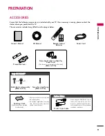
Page 10: ...ailable for all models Copyright 2007 LGE All Rights Reserved D sub 15 pin Cable 1 5V 1 5V Owner s Manual Power Cord Remote Control Batteries IN PU T FA V MU TE TV STB POW ER Q MEN U MEN U AV MODE RE TU RN ENTER VOL CH 1 2 3 4 5 6 7 8 0 9 FLASHBK P A G E DVD VCR CD Manual When using the VGA D sub 15 pin cable PC connection the user must use shielded signal interface cables with ferrite cores to ma...

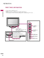
Page 11: ...th your TV use it POWER Button Power Standby Indicator Illuminates red in standby mode Illuminates blue when the set is switched on Can be adjusted using P Po ow we er r I In nd di ic ca at to or r in the OPTION menu G G p p 6 67 7 CH VOL MENU INPUT ENTER CHANNEL Buttons VOLUME Buttons ENTER Button MENU Button INPUT Button Intelligent Sensor Adjusts picture according to the surrounding conditions ...

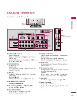
Page 12: ... AUDIO RGB DVI 1 8 headphone jack for analog PC audio input REMOTE CONTROL IN PORT For a wired remote control RS 232C IN CONTROL SERVICE PORT Used by third party devices ANTENNA CABLE IN Connect over the air signals to this jack Connect cable signals to this jack DIGITAL AUDIO OUT Digital audio output for use with amps and home theater systems Includes an optical and coaxial connection Note In sta...

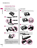
Page 13: ...n from damage 1 INSTALLATION Only 37 42LG5 DETACHMENT Carefully place the TV screen side down on a cushioned surface to protect the screen from damage 1 Loose the bolts from TV 2 Detach the stand from TV 3 After removing the stand install the included p pr ro ot te ec ct ti io on n c co ov ve er r over the hole for the stand Press the P PR RO OT TE EC CT TI IO ON N C CO OV VE ER R into the TV unti...

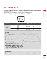
Page 14: ...re shown in the table G G When purchasing our wall mount kit a detailed installation manual and all parts necessary for assembly are provided G G Do not use screws longer then the standard dimen sion as they may cause damage to the inside to the TV G G For wall mounts that do not comply with the VESA standard screw specifications the length of the screws may differ depending on their specifica tio...

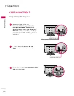
Page 15: ...er cable with the PROTECTIVE BRACKET and the screw as shown It will help prevent the power cable from being removed by accident Install the CABLE MANAGEMENT CLIP as shown CABLE MANAGEMENT CLIP PROTECTIVE BRACKET This feature is not available for all models 1 2 Put the cables inside the CABLE MANAGEMENT CLIP and snap it closed 3 Image shown may differ from your TV ...

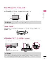
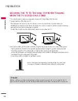
Page 16: ... G Ensure adequate ventilation by following the clearance recommendations G G Do not mount near or above any type of heat source CAUTION ATTACHING THE TV TO A DESK Only 37 42LG5 The TV must be attached to a desk so it cannot be pulled in a forward backward direction potentially causing injury or damaging the product G G To prevent TV from falling over the TV should be securely attached to the floo...

Page 17: ...e upper holes Secure the wall brackets with the bolts sold separately to the wall Match the height of the bracket that is mounted on the wall to the holes in the product Ensure the eye bolts or brackets are tightened securely Use a sturdy rope sold separately to tie the product It is safer to tie the rope so it becomes horizontal between the wall and the product You should purchase necessary compo...

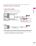
Page 18: ...axial Wire 75 ohm Single family Dwellings Houses Connect to wall jack for outdoor antenna Be careful not to bend the copper wire when connecting the antenna Copper Wire To improve the picture quality in a poor signal area please purchase a signal amplifier and install properly If the antenna needs to be split for two TV s install a 2 Way Signal Splitter If the antenna is not installed properly con...

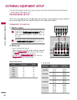
Page 19: ...set top box operation Select the C Co om mp po on ne en nt t 1 1 input source on the TV using the I IN NP PU UT T button on the remote control If connected to C CO OM MP PO ON NE EN NT T I IN N2 2 input select the C Co om mp po on ne en nt t 2 2 input source on the TV To prevent the equipment damage never plug in any power cords until you have finished connecting all equipment Image shown may diff...

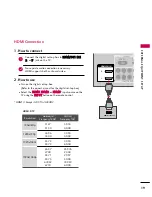
Page 20: ... set top box Select the H HD DM MI I1 1 H HD DM MI I2 2 or H HD DM MI I3 3 input source on the TV using the I IN NP PU UT T button on the remote control 2 1 HDMI DTV Horizontal Vertical Frequency KHz Frequency Hz 31 47 59 94 31 50 60 00 44 96 59 94 45 00 60 00 33 72 59 94 33 75 60 00 26 97 23 976 27 00 24 00 33 71 29 97 33 75 30 00 67 432 59 939 67 50 60 00 Resolution 720x480p 1280x720p 1920x1080i...

Page 21: ...ox Refer to the owner s manu al for the digital set top box Select the H HD DM MI I1 1 H HD DM MI I2 2 or H HD DM MI I3 3 input source on the TV using the I IN NP PU UT T button on the remote control 2 1 DVI to HDMI Connection G G A DVI to HDMI cable or adapter is required for this connection DVI doesn t support audio so a separate audio connection is necessary NOTE RGB IN COMPONENT IN AUDIO RGB D...

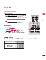
Page 22: ...Y green PB blue and PR red Connect the audio outputs of the DVD to the C CO OM MP PO ON NE EN NT T I IN N A AU UD DI IO O1 1 jacks on the TV 1 How to connect 2 How to use Turn on the DVD player insert a DVD Select the C Co om mp po on ne en nt t 1 1 input source on the TV using the I IN NP PU UT T button on the remote control If connected to C CO OM MP PO ON NE EN NT T I IN N 2 2 input select the ...

Page 23: ...e A AV V1 1 input source on the TV using the I IN NP PU UT T button on the remote control Refer to the DVD player s manual for operating instructions 2 1 HDMI Connection Connect the HDMI output of the DVD to the H HD DM MI I D DV VI I I IN N1 1 2 2 or 3 3 jack on the TV No separate audio connection is necessary HDMI supports both audio and video 1 How to connect 2 How to use Select the H HD DM MI ...

Page 24: ...anty ANTENNA CABLE IN E COAXIAL UDIO OUT L R S VIDEO VIDEO OUTPUT SWITCH ANT IN ANT OUT EO L R MONO AUDIO AUDIO OUT Wall Jack Antenna 1 2 Connect the RF antenna out socket of the VCR to the A AN NT TE EN NN NA A C CA AB BL LE E I IN N sock et on the TV Connect the antenna cable to the RF antenna in socket of the VCR 1 How to connect 2 How to use Set VCR output switch to 3 or 4 and then tune TV to ...

Page 25: ...on the remote control If connected to A AV V I IN N2 2 select A AV V2 2 input source on the TV 1 G G Do not connect to both Video and S Video at the same time In the event that you connect both Video and the S Video cables only the S Video will work CAUTION G G S Video provides better quality than composite Use it when available NOTE S Video Connection NT IN AUDIO RGB DVI REMOTE CONTROL IN ANTENNA...

Page 26: ... O jacks between TV and external equipment Match the jack colors Video yellow Audio Left white and Audio Right red 1 How to connect 2 How to use Select the A AV V2 2 input source on the TV using the I IN NP PU UT T button on the remote control If connected to A AV V I IN N1 1 input select the A AV V1 1 input source on the TV Operate the corresponding external equipment 1 1 ...

Page 27: ...use Turn on the PC and the TV Select the R RG GB B P PC C input source on the TV using the I IN NP PU UT T button on the remote control 2 1 DVI to HDMI Connection Connect the DVI output of the PC to the H HD DM MI I D DV VI I I IN N 1 1 2 2 or 3 3 jack on the TV Connect the PC audio output to the A AU UD DI IO O R RG GB B D DV VI I jack on the TV 1 How to connect 2 How to use Turn on the PC and th...

Page 28: ...the resolution vertical pattern contrast or bright ness If noise is present change the PC output to another resolution change the refresh rate to another rate or adjust the brightness and contrast on the PICTURE menu until the picture is clear G G Avoid keeping a fixed image on the screen for a long period of time The fixed image could become permanently imprinted on the screen G G The synchroniza...

Page 29: ...djusted Select P PI IC CT TU UR RE E Select S Sc cr re ee en n R RG GB B P PC C Select R Re es so ol lu ut ti io on n Select the desired resolution 1024 x 768 1280 x 768 1360 x 768 Auto config Resolution G Position Size Phase Reset SCREEN Move Prev MENU 1MENU 3 4 2 ENTER ENTER ENTER 5 ENTER Enter Move PICTURE R G Backlight 80 Contrast 90 Brightness 50 Sharpness 60 Color 60 Tint 0 Advanced Control ...

Page 30: ...fig G Resolution Position Size Phase Reset SCREEN Move Prev MENU To Set 3 2 ENTER ENTER Select Y Ye es s 4 ENTER Start Auto Configuration 5 ENTER Select P PI IC CT TU UR RE E 1MENU If the position of the image is still not correct try Auto adjustment again If picture needs to be adjusted again after Auto adjustment in RGB PC you can adjust the P Po os si it ti io on n S Si iz ze e or P Ph ha as se...

Page 31: ...REEN Move Prev MENU 3 ENTER 4 ENTER P Po os si it ti io on n This function is to adjust pic ture to left right and up down as you prefer S Si iz ze e This function is to minimize any vertical bars or stripes visible on the screen background And the horizontal screen size will also change P Ph ha as se e This function allows you to remove any horizontal noise and clear or sharpen the image of chara...

Page 32: ...ates only in RGB PC mode Auto config Position Resolution Size Phase Reset G SCREEN Move Prev MENU To Set Select R Re es se et t 3 ENTER Select P PI IC CT TU UR RE E Select S Sc cr re ee en n R RG GB B P PC C 1MENU 2 ENTER Select Y Ye es s 4 ENTER 5 ENTER Yes No Enter Move PICTURE R G Backlight 80 Contrast 90 Brightness 50 Sharpness 60 Color 60 Tint 0 Advanced Control Reset Screen RGB PC E ...

Page 33: ...T SETUP AV IN 2 L MONO R AUDIO VIDEO HDMI IN 3 USB IN Connect the USB device to the U US SB B I IN N jack on the side of TV 1 How to connect 1 2 How to use After connecting the U US SB B I IN N jack you use the USB function G G p p 4 48 8 1 Except 42 47 52LG50DC ...

Page 34: ...he laser beam may damage your vision G G Block the SPDIF out optical coaxial about the contents with ACP Audio Copy Protection function CAUTION Connect one end of the optical or coaxial cable to the TV s O OP PT TI IC CA AL L or C CO OA AX XI IA AL L port of D DI IG GI IT TA AL L A AU UD DI IO O O OU UT T Connect the other end of the optical or coaxial cable to the digital audio input on the audio...

Page 35: ...ase use only a USB storage device which was formatted as a FAT or NTFS file system provided with the Windows operating system In case of a storage device formatted as a different utility pro gram which is not supported by Windows it may not be recognized G G Please connect power to a USB storage device which requires an external power supply If not the device may not be recognized G G Please conne...

Page 36: ...rked photos G G D De el le et te e Delete the selected photo item G G C Cl lo os se e Close the pop up menu USB Device Page 2 3 No Marked Photo List Upper Free Space 150MB 1366x768 125KB KY101 06 10 2008 KY102 04 03 2008 JMJ001 01 01 2000 JMJ002 06 15 2008 JMJ003 04 03 2008 JMJ004 02 18 2008 KY103 03 30 2008 KY104 06 19 2008 KY105 01 31 2008 JMJ005 05 13 2008 JMJ006 05 26 2008 JMJ007 02 18 2008 JM...

Page 37: ...slide show If no photo is selected all photos in the cur rent folder are displayed during slide show Set the time interval of the slide show in O Op pt ti io on n A slide show continues for a maximum of 4 hours After 4 hours the slide show will end and go to TV mode or external input mode G G R Ro ot ta at te e Rotate photos Rotates the photo 90 180 270 360 clockwise G G D De el le et te e Delete ...

Page 38: ...e Mark Exit CH FAV RETURN PopUp Menu Play Time Title Upper Good Bye Arirang USB Device Page 1 1 No Marked Music List Upper Free Space 150MB 3945 KB 128 Kbps Drive1 Arirang Move Move Page Mark Exit CH FAV RETURN PopUp Menu Play Time Title Upper Good Bye Arirang 05 30 04 12 3945 KB 128 Kbps Play Mark All Delete Close G G P Pl la ay y During stop Play the selected music Once a song finishes playing t...

Page 39: ...ended period of time NOTE G G When music is playing is displayed in front of the music play time G G A damaged or corrupted music file that does not play displays 00 00 as the play time G G Music files with copy protection will not play G G Press E EN NT TE ER R A A or R RE ET TU UR RN N button to stop the screen saver G G This TV can not play music files less than 16 Kbytes ...

Page 40: ... channel The problem may be with the broadcast Is the power cord inserted into wall power outlet Check your antenna direction and or location Test the wall power outlet plug another product s power cord into the outlet where the product s power cord was plugged in This is normal the image is muted during the product startup process Please contact your service center if the picture has not appeared...

Page 41: ...e Incorrect position Picture OK No sound Unusual sound from inside the product No sound when connecting HDMI USB No output from one of the speakers T Th he e a au ud di io o f fu un nc ct ti io on n d do oe es s n no ot t w wo or rk k Press the VOL or VOLUME button Sound muted Press MUTE button Try another channel The problem may be with the broadcast Are the audio cables installed properly Adjust...

Page 42: ... water and a little fabric softener or dish washing detergent Wring the cloth until it s almost dry and then use it to wipe the screen Make sure the excess water is off the screen and then let it air dry before you turn on your TV Cleaning the Cabinet To remove dirt or dust wipe the cabinet with a soft dry lint free cloth Please be sure not to use a wet cloth Extended Absence G G If you expect to ...

Page 43: ...2LG50DC 42LG50DC UG 42LG55 42LG55 UE 36 8 x 26 9 x 1 1 5 inches 936 4 x 685 4 x 293 4 mm 36 8 x 24 1 x 3 4 inches 936 4 x 612 8 x 88 0 mm 40 3 pounds 18 3 kg 34 3 pounds 15 6 kg 40 7 x 28 9 x 1 1 5 inches 1034 0 x 735 0 x 294 0 mm 40 7 x 26 1 x 3 5 inches 1034 0 x 663 0 x 91 0 mm 54 0 pounds 24 5 kg 48 5 pounds 22 0 kg MODELS 47LH50 47LH50 UC 47LG50DC 47LG50DC UG 47LG55 47LG55 UE 52LH50 52LH50 UC ...

Page 44: ...s correctly If the component does not operate correctly the remote control requires programming to operate the device Turn on the component to be programmed then press the corresponding mode button such as S ST TB B on the remote control The remote control button of the desired device is illuminated Press the M ME EN NU U and M MU UT TE E buttons simultaneously and the remote control is ready to b...

Page 45: ...5 046 059 MINOLTA 013 020 MITSUBISHI 013 020 045 046 049 051 059 061 151 MTC 034 040 MULTITECH 024 034 NEC 012 023 039 043 048 NORDMENDE 043 OPTONICA 053 054 PANASONIC 066 070 074 083 133 140 145 PENTAX 013 020 031 033 063 PHILCO 031 034 067 PHILIPS 031 033 034 054 067 071 101 PILOT 101 PIONEER 013 021 048 PORTLAND 108 PULSAR 072 QUARTZ 01 1 014 QUASAR 033 066 075 145 RCA 013 020 033 034 040 041 0...

Page 46: ... 070 PACE SKY SATELLITE 143 PANASONIC 060 142 PANSAT 121 PERSONAL CABLE 1 17 PHILIPS 071 PICO 105 PRESIDENT 019 102 PRIMESTAR 030 1 10 1 1 1 PROSAT 072 RCA 066 106 REALISTIC 043 074 SAMSUNG 123 SATELLITE SERVICE CO 028 035 047 057 085 SCIENTIFIC ATLANTA 032 138 SONY 103 STARCAST 041 SUPER GUIDE 020 124 125 TEECOM 023 026 075 087 088 090 107 130 137 TOSHIBA 002 127 UNIDEN 016 025 042 043 044 045 04...

Page 47: ...C5 C6 C7 D0 D1 D2 D3 D4 D5 D6 D7 D0 D1 D2 D3 D4 D5 D6 D7 Lead code Low custom code High custom code Data code Data code Repeat code Tf 4 5 ms 9 ms 2 25 ms 9 ms 0 55 ms 0 56 ms 1 12 ms 0 56 ms 2 24 ms Tf Tf Tf 108ms 455KHz Bit 0 Bit 1 1 How to Connect Connect your wired remote control to the Remote Control port on the TV 2 Remote Control IR Codes Output waveform Single pulse modulated with 37 917KH...

Page 48: ...MODE Remote control Button B0 PLAY Remote control Button BA PAUSE Remote control Button B1 STOP Remote control Button BD REC Remote control Button 8F REW Remote control Button 8E FF Remote control Button Except 42 47 52LG50DC D6 TV Discrete IR Code TV Input Selection C4 POWER ON Discrete IR Code Only Power On C5 POWER OFF Discrete IR Code Only Power Off 5A AV1 Discrete IR Code AV1 Input Selection ...

Page 49: ...test functionality using telenet software O VI REMOTE CONTROL IN R AUDIO OPTICAL COAXIAL DIGITALAUDIO OUT AV IN 1 VIDEO L R MONO AUDIO S VIDEO AUDIO OUT RS 232C IN CONTROL SERVICE Type of Connector D Sub 9 Pin Male No Pin Name 1 No connection 2 RXD Receive data 3 TXD Transmit data 4 DTR DTE side ready 5 GND 6 DSR DCE side ready 7 RTS Ready to send 8 CTS Clear to send 9 No Connection 1 6 5 9 PC Com...

Page 50: ...Sub 9 7 Wire Configuration Serial female female NULL modem cable 3 Wire Configurations Not standard Select O OP PT TI IO ON N Select S Se et t I ID D Choose the desired TV ID number The adjustment range of Set ID is 1 99 1MENU 3 2 ENTER ENTER 4RETURN Return to the previous menu MENU Return to TV viewing Enter Move OPTION Language English Input Label SIMPLINK On Key Lock Off Caption Off Set ID 1 Po...

Page 51: ...t send the status during the standby mode O OK K A Ac ck kn no ow wl le ed dg ge em me en nt t The TV transmits ACK acknowledgement based on this for mat when receiving normal data At this time if the data is data read mode it indicates present status data If the data is data write mode it returns the data of the PC computer In this model TV will not send the status during the standby mode Data Fo...

Page 52: ... d k k d d To select screen mute on off Transmission k d Set ID Data Cr Data 00 Screen mute off Picture on Data 01 Screen mute on Picture off Acknowledgement d Set ID OK NG Data x 0 05 5 V Vo ollu um me e M Mu ut te e C Co om mm ma an nd d k k e e To control volume mute on off You can also adjust mute using the MUTE button on remote control Transmission k e Set ID Data Cr Data 00 Volume mute on Vo...

Page 53: ...sion k m Set ID Data Cr Data 00 Lock off Data 01 Lock on Acknowledgement m Set ID OK NG Data x If you re not using the remote control and front panel controls on the TV use this mode When main power is on off remote control lock is released 1 14 4 T Tr re eb blle e C Co om mm ma an nd d k k r r To adjust treble You can also adjust treble in the AUDIO menu Transmission k r Set ID Data Cr Data Min 0...

Page 54: ...ata02 Data03 Data04 Data05 Cr Digital channels have a Physical Major and Minor channel number The Physical number is the actual digital channel number the Major is the number that the channel should be mapped to and the Minor is the sub channel Since the ATSC tuner automatically maps the channel to the Major number the Physical number is not required when sending a command Data 00 Physical Channel...

Page 55: ...3 Data 05 0010 0010 in binary 22 Total ma 00 00 00 1E 00 03 22 Acknowledgement a Set ID OK Data00 Data01 Data02 Data03 Data04 x a Set ID NG Data00 x 2 20 0 C Ch ha an nn ne ell A Ad dd d D De ell C Co om mm ma an nd d m m b b To add and delete the channels Transmission m b Set ID Data Cr Data 00 Channel Delete Data 01 Channel Add Acknowledgement b Set ID OK NG Data x 2 21 1 K Ke ey y C Co om mm ma...

Page 56: ...e used with this System Canadian DOC Notice This Class B digital apparatus meets all requirements of the Canadian Interference Causing Equipment Regulations Cet appareil numérique de la classe B respecte toutes les exigences du Règlement sur le matériel brouilleur du Canada CE Conformity Notice for Europe Products with the CE Marking comply with the EMC Directive 89 336 EEC and LOW VOLTAGE Directi...

Page 57: ...one or more stages The length of time to reactivate the system unit shall be reasonable for the user Labelled products must meet strict environmental demands for example in respect of the reduction of electrical and magnetical fields as well as work load and visual ergonomics Below you will find a brief summary of the ecological requirements met by this product The complete ecological criteria doc...

Page 58: ...ty Emissions Electromagnetic fields Noise emissions Ecology The product must be prepared for recycling and the manufacturer must have a certified environmental management system such as EMAS or ISO 14 001 Restrictions on chlorinated and brominated flame retardants and polymers heavy metals such as cadmium mercury and lead The requirements included in this label have been developed by TCO Developme...

Page 59: ...ser Recyclingprogramm erfahren möchten wenden Sie sich bitte an Ihren lokalen LG Händler oder einen Unternehmensvertreter von LG Wir richten unsere Firmenpolitik auf eine sauberere Umwelt hin aus indem wir umweltspezifische Aspekte als wichtigen Punkt in die Weiterentwicklung unseres Unternehmens einfließen lassen Zusätzliche Informationen über unsere grüne Firmenpolitik erhalten Sie auf unserer W...

Page 60: ...limpio de LG en 1994 y este ideal ha servido para guiar nuestros principios empresariales desde entonces La Declaración es la base que nos ha permitido llevar a cabo tareas que respetan el medio ambiente siempre teniendo en cuenta aspectos sociales económicos y medioambientales Promocionamos actividades orientadas a la conservación del medio ambiente y desarrollamos nuestros productos específicame...

Page 61: ...houden bij het ontwikkelen onze producten specifiek rekening met de milieuvriendelijkheid van onze producten Wij minimaliseren het gebruik van schadelijke stoffen in onze producten Er wordt bijvoorbeeld geen cadmium verwerkt in onze monitors Nederlands Informatie met betrekking tot recycling Deze monitor bevat materialen die schadelijk zouden kunnen zijn voor het milieu Het is belangrijk dat deze ...

Page 62: ...ÏÔÓÌÂÌÚ Û ÛÚ ÚÓ Ë ÌÓ ËÒÔÓÎ ÁÓ Ì Ë ÛÚËÎËÁË Ó Ì ÚÓ ÂÏˇ Í Í Â Ì Â Â ÂÒÚ Ë ÚˇÊÂÎ Â ÏÂÚ ÎÎ Û ÛÚ Ó ÓÚ Ì Ò ÔÓÏÓ ÍÓÎÓ Ë ÂÒÍË Ô ËÂÏÎÂÏÓ Ó ÏÂÚÓ ÓΠÔÓ Ó ÌÓÈ ËÌÙÓ Ï ˆËÂÈ ÔÓ Ì ÂÈ Ô Ó ÏÏ ÛÚËÎËÁ ˆËË ÓÚıÓ Ó Ó ÈÚÂÒ Í ÏÂÒÚÌÓÏÛ ÔÓÒÚ ËÍÛ ËÎË Ô Â ÒÚ ËÚÂÎ ÍÓ ÔÓ ˆËË LG Ã Ó ËÂÌÚË ÛÂÏÒˇ Ì Ó ÂÒÔ ÂÌË ÍÓÎÓ Ë ÂÒÍÓÈ ÂÁÓÔ ÒÌÓÒÚË ÒÚ ˇ Ò  ˆÂÎ ÎÓ Î ÌÛ Á ËÚÛ ÓÍ ÛÊ ÂÈ Ò Â ƒÓÔÓÎÌËÚÂÎ ÌÛ ËÌÙÓ Ï ˆË Ó Ì ÂÈ ÔÓÎËÚËÍ ÔÓ Óı Ì ÓÍ ÛÊ...

Page 63: ...geven met het huishoudelijk afval maar moeten worden ingeleverd bij speciale inzamelingspunten die door de lokale of landelijke overheid zijn aangewezen 3 De correcte verwijdering van uw oude toestel helpt negatieve gevolgen voor het milieu en de menselijke gezondheid voorkomen Smaltimento delle apparecchiature obsolete Kassering av din gamla apparat Uw oude toestel wegdoen 1 Ce symbole représenta...

Page 64: ...saat ottamalla yhteyden paikallisiin viranomaisiin kierrätyskeskukseen tai myymälään josta ostit laitteen 1 Når der er et tegn med et kryds over en skraldespand betyder det at produktet er omfattet af EU direktiv 2002 96 EC 2 Alle elektriske og elektroniske produkter skal smides ud et andet sted end gennem den kommunale affaldsordning ved hjælp af specielle indsamlingsfaciliteter der er organisere...

Page 65: ...Regulatory Information cont 10 Portuguese Slovak Czech Croatian Hungarian Polish ...

Page 66: ...Regulatory Information cont 11 Estonian Latvian Lithuanian ...

Page 67: ......

Reviews: