background image

Mechanical Installation

Mounting Methods

General Information

Select the appropriate orientation to maximize

sunlight exposure.

In order to prevent water from entering the

junction box, which could present a safety hazard,

module should not be mounted such that the

front/top glass faces downward.

Clearance between the solar module frames and

structures such as roofs or ground is required to

prevent wiring damage and to allow air to

circulate behind the solar module. The

recommended standoff height is a minimum of

100mm.

When installed on a roof, the solar module must

be mounted over a fire-resistant roof covering

rated for the application. The fire resistance of the

solar module from LG Electronics is class C after

ANSI/UL790.

The solar module is only IEC listed for use when

its factory frame is fully intact.

Do not remove or alter the solar module frame.

Creating additional mounting holes may damage

the solar module and reduce the strength of the

frame.

A 6mm gap between module frames should be     

allowed to avoid tension from thermal expansion.

The solar module may be mounted using the

   following methods: (*Torque:8~12Nm )

When installing modules in heavy snow areas,

special care should be taken to install the

modules in a manner that provides sufficient

design strength while meeting local code

requirements.

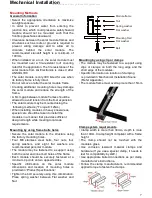
Mounting by using frame bolts holes

Secure the solar module to the structure using

the factory mounting holes.

Four M8 stainless steel bolts, four nuts, four

spring washers, and eight flat washers are

recommended per solar module.

The module may be fastened to a support using

both the outer and inner bolt holes of the frame.

Each module should be securely fastened at a

minimum 4 points on two opposite sides.

Specific information on the solar module

dimensions and location of mounting holes is

provided in ‘Product Specifications’.

Tighten the bolt securely using this combination.

Place spring washer between Flat washer and

Nut.

Mounting by using clip or clamps

The module may be fastened to a support using

clips or clamps on both the long edge and the

short edge of the modules.

Specific information on location of clamping

   is provided in ‘Mechanical Installation Scene’

   (Refer Appendix.).

The module frame must overlap more than 15mm.

Clamp system requirements

Clamp width is more than 30mm, depth is more

than 10mm. Clamp height compliant with a frame

height.

The clamp should not be touched with the

module’s glass.

Use corrosion resistant material clamps and

hardware.(If you use a special clamp, it needs to

test for compatibility by LGE.)

Use appropriate bolted connections as per clamp

manufacturer’s instructions.

Follow the clamp manufacturer’s recommended

applied torque to fasten the clamps.

7

Module frame

Bolt

Flat washer

Flat washer

Spring washer

Nut

Mounting Rail

All manuals and user guides at all-guides.com

Summary of Contents for 315Q1K-A5

Page 1: ...before operating your set and retain it for future reference www lg solar com Installation manual PV Solar MODULE P NO MFL69724902 Rev 00 N TYPE MODELS LGXXXQ1C K A5 All manuals and user guides at all guides com a l l g u i d e s c o m ...

Page 2: ...ical Installation 6 5 Product Specifications 8 6 Disclaimer of Liability Disposal 10 7 Transporting and Storage 10 8 Appendix 11 Revisions Table Date Version Description of change Remark 2016 09 02 1 0 1st edition 2016 12 07 2 0 Add New Products Black Model 2 All manuals and user guides at all guides com ...

Page 3: ...ould be more than 4 times the cable diameter at least Please use proper equipment connector wire and buttress for system configuration of the module It may result in damage or failure of the product Do not perform installation in rainy heavily windy or snowy days It may result in safety accident Do not make holes in the frame or glass of the module It may decrease the strength of the frame or brea...

Page 4: ... time of installation Make sure flammable gases are not generated near the installation site Do not work alone Please work as part of a team of two or more people Wear a safety belt if working high above the ground Contact with electrically active parts of the panels such as terminals can result in burns sparks and lethal shock whether the panel is connected or disconnected Even partial shadowing ...

Page 5: ...of each module connected in series should be same The maximum number of series connected modules can be determined by basis on max system voltage the 125 safety factor and the module Voc which can be checked in Product Specifications in this document Do not exceed 80 of maximum system voltage The maximum solar module configuration can be found in Product Specifications Series connection for more v...

Page 6: ...r modules from LG meet the conditions of safety class Ⅱ The national directives must be respected Module frame Bolt Flat washer Star washer Cup washer Grounding wire Spring washer Nut Flat washer 6 Module Mounting The LG Electronics LGE Limited Warranty for solar modules is contingent upon modules being mounted in accordance with the requirements described in this section The solar modules are in ...

Page 7: ...ts Mounting by using frame bolts holes Secure the solar module to the structure using the factory mounting holes Four M8 stainless steel bolts four nuts four spring washers and eight flat washers are recommended per solar module The module may be fastened to a support using both the outer and inner bolt holes of the frame Each module should be securely fastened at a minimum 4 points on two opposit...

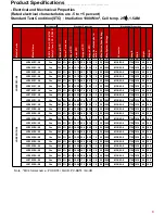
Page 8: ...1700 1016 40 18 5 LG380Q1C A5 Yes 380 3 42 9 10 84 37 4 10 17 18 20 1000 MC4 05 8 1700 1016 40 18 5 LG385Q1C A5 Yes 385 3 42 9 10 85 37 7 10 22 18 20 1000 MC4 05 8 1700 1016 40 18 5 LG315Q1K A5 Yes 315 3 41 4 10 00 34 7 9 09 19 20 1000 MC4 05 8 1700 1016 40 18 5 LG320Q1K A5 Yes 320 3 41 6 10 06 34 9 9 18 19 20 1000 MC4 05 8 1700 1016 40 18 5 LG325Q1K A5 Yes 325 3 41 9 10 11 35 1 9 27 19 20 1000 MC...

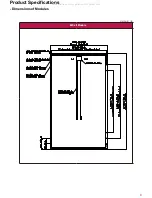
Page 9: ...Product Specifications Dimensions of Modules 9 60Cell Module Unit mm in All manuals and user guides at all guides com ...

Page 10: ...eparately from the municipal waste stream 2 Old electrical products can contain hazardous substances so correct disposal of your old appliance will help prevent potential negative consequences for the environment and human health Your old appliance may contain reusable parts that could be used to repair other products and other valuable materials that can be recycled to conserve limited resources ...

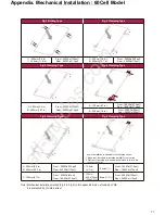
Page 11: ...e A B B A C C B A 4 point installation is allowed in the following cases 1 Slope roof If module is installed parallel to the rooftop d n i w s a h c u s d n a t s l a n o i t i d d a n a h t i w d e l l a t s n i f I f o o r t a l F 2 A 200mm 5 9 in B 400mm 15 7 in Front 6000Pa 125psf Rear 5400Pa 113psf m m 0 2 1 A 4 7 in 4point Front 1800Pa 37 5psf Rear 1800Pa 37 5psf C 120mm 4 7in Front 3200Pa 6...

Page 12: ...gu Seoul 150 721 Korea Contact solarinfo lge com http www lg solar com This document is subject to change without notice LG LG logo and Life s Good are trademarks of LG Electronics Inc worldwide Trademarks and intellectual properties of LG Electronics Inc are protected by international copyright laws Document II BC IEC V1 EN 201609 All manuals and user guides at all guides com ...

Reviews: