background image

EXTERNAL EQ

UIPMENT SETUP

30

EXTERNAL EQUIPMENT SETUP

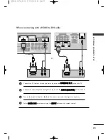
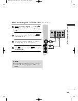
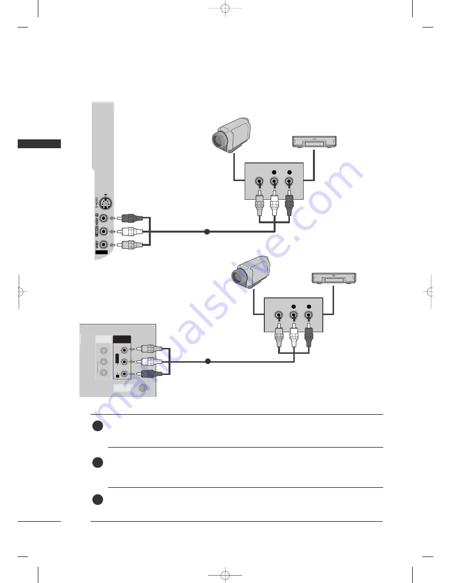
AV IN 2

V IN 2

L

R

VIDEO

Camcorder

Video Game Set

1

OTHER A/V SOURCE SETUP

Connect the A

AU

UD

DIIO

O/V

VIID

DE

EO

O jacks between TV and external equipment. Match the jack colors.

(Video = yellow, Audio Left = white, and Audio Right = red)

Select 

A

A V

V 2

2

input source using the IIN

NP

PU

UT

T button on the remote control.

If connected to A

AV

V   IIN

N1

1, select 

A

A V

V 1

1

input source.

Operate the corresponding external equipment. 

Refer to external equipment operating guide.

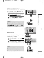
1

2

3

or

L

R

VIDEO

ANTENNA

IN

AV IN

L/

MONOMONO

R

AUDIOAUDIO

VIDEOVIDEO

VIDEO

AUDIO

COMPONENT IN

1

2

1

2

HDMI IN

HDMI/DVI IN

RGB IN (PC)

AUDIO IN
(RGB/DVI)

AV OUT

V OUT

RS-232C IN

(CONTROL & SERVICE)

VARIABLE ARIABLE 

AUDIO OUTAUDIO OUT

1

Camcorder

Video Game Set

MFL41469207en-Edit1  8/22/08 8:54 AM  Page 30

Summary of Contents for 26LG30R

Page 1: ...et See the label attached on the back cover and quote this information to your dealer when you require service LCD TV PLASMA TV OWNER S MANUAL LCD TV MODELS 26LG30R 32LG30R 37LG30R 42LG30R 47LG30R 32LG50FR 42LG50FR PLASMA TV MODELS 42PG20R 50PG20R 32PC5RA P NO MFL41469207 0808 REV08 www lge com MFL41469207en Edit1 8 22 08 8 54 AM Page 1 ...

Page 2: ...MFL41469207en Edit1 8 22 08 8 54 AM Page 2 ...

Page 3: ...he exclamation point within an equilateral triangle is intended to alert the user to the presence of important operating and maintenance servicing instructions in the literature accompanying the appliance TO REDUCE THE RISK OF ELECTRIC SHOCK DO NOT REMOVE COVER OR BACK NO USER SERVICEABLE PARTS INSIDE REFER TO QUALIFIED SERVICE PERSONNEL WARNING CAUTION TO REDUCE THE RISK OF FIRE AND ELECTRIC SHOC...

Page 4: ...Follow all instructions Do not use this apparatus near water Clean only with dry cloth Do not block any ventilation openings Install in accordance with the manufacturer s instructions Do not install near any heat sources such as radiators heat registers stoves or other apparatus including amplifiers that produce heat When mounting a TV it on the wall make sure not to install TV by the hanging powe...

Page 5: ...d of your appliance and if its appearance indicates dam age or deterioration unplug it discontinue use of the appliance and have the cord replaced with an exact replacement part by an authorized servicer Protect the power cord from physical or mechanical abuse such as being twisted kinked pinched closed in a door or walked upon Pay particular attention to plugs wall outlets and the point where the...

Page 6: ...Selection 42 Volume Adjustment 42 Quick Menu 43 On Screen Menus Selection 44 Channel Search 45 Auto Turning 45 Manual Turning Adding Deleting Channels 46 Fine Tuning Adjustment 47 Booster 48 Favorite Channels Setup 49 Key Lock 50 AV Mode 51 SimpLink 52 PICTURE CONTROL Watching PIP Picture In Picture 54 Picture Size Aspect Ratio Control 55 Preset Picture Settings 56 Picture Mode Preset 56 Auto Colo...

Page 7: ...ng Audio Out 76 On Screen Menus Language Selection 76 Closed Caption 77 TIME SETTING Clock Setup 78 Auto On Off Time Setting 79 Sleep Timer Setting 80 Auto Shut off Setting 81 APPENDIX Troubleshooting 82 Maintenance 83 Product Specifications 84 Programming the Remote Control 86 IR Codes 88 External Control Through RS 232C 90 MFL41469207en Edit1 8 22 08 8 54 AM Page 5 ...

Page 8: ...e screen O On n D Di is sp po os sa al l O On nl ly y H Hg g l la am mp p u us se ed d L LC CD D T TV V a The fluorescent lamp used in this product contains a small amount of mercury b Do not dispose of this product with general household waste c Disposal of this product must be carried out in accordance to the regulations of your local authority PREPARATION Ferrite core can be used to reduce the ...

Page 9: ... VO L C H 1 2 3 4 5 6 7 8 0 9 Q VIEW PI P Remote Control F Fo or r P Pl la as sm ma a T TV V m mo od de el ls s Bolts for stand assembly Refer to P 13 Protection cover Refer to p 18 This accessories can be differ ent from the figures shown here depending on your models Only 42PG20 F Fo or r L LC CD D T TV V m mo od de el ls s Protection cover Refer to p 18 This accessories can be differ ent from t...

Page 10: ...utton CH VOL MENU INPUT ENTER CH VOL MENU INPUT ENTER Remote Control Sensor POWER Button Power Standby Indicator Illuminates red in standby mode Illuminates green when the set is switched on Plasma TV Models Only 32PC5 PR VOL OK MENU INPUT Power Standby Indicator illuminates red in standby mode illuminates green when the TV is switched on Remote Control Sensor PR VOL OK MENU INPUT INPUT Button MEN...

Page 11: ...ched on Can be adjusted P Po ow we er r I In nd di ic ca at to or r in the Option menu CH VOL MENU INPUT ENTER CHANNEL Buttons VOLUME Buttons ENTER Button MENU Button INPUT Button Remote Control Sensor Intelligent Sensor Adjusts picture according to the surrounding condi tions Only 32 42LG50 MFL41469207en Edit1 8 22 08 8 54 AM Page 9 ...

Page 12: ...ABLE OUT AUDIO IN RGB DVI AV OUT AV IN L MONO R AUDIO VIDEO VIDEO AUDIO COMPONENT IN HDMI IN HDMI DVI IN 1 2 RGB IN PC ANTENNA IN 1 2 RS 232C IN CONTROL SERVICE AUDIO IN RGB DVI AV OUT AV IN L MONO R AUDIO VIDEO 8 VIDEO VIDEO AUDIO AUDIO COMPONENT COMPONENT IN IN HDMI IN HDMI IN HDMI DVI IN HDMI DVI IN 1 2 RGB IN PC RGB IN PC ANTENNA ANTENNA IN 1 2 RS 232C IN RS 232C IN CONTROL CONTROL SER SERVICE...

Page 13: ...32C IN CONTROL VIDEO AUDIO VIDEO MONO AUDIO HDMI DVI IN ANTENNA IN 1 2 HDMI IN RGB IN IN 1 OUT AV VARIABLE AUDIO OUT RGB DVI 2 1 6 4 3 5 7 2 2 S VIDEO 2 8 10 9 2 2 2 S VIDEO 3 10 9 1 Only 32 42LG50 Only 26 32 37 42 47LG30 MFL41469207en Edit1 8 22 08 8 54 AM Page 11 ...

Page 14: ...nt video audio device to these jacks ANTENNA IN Connect over the air signals to this jack RGB IN RGB PC Connect the output from a PC AUDIO RGB DVI Connect the audio from a PC or DTV RS 232C IN CONTROL Except 32 42LG50 For external control devices Power Cord Socket For operation with AC power Caution Never attempt to operate the TV on DC power AV Audio Video IN 2 Connect audio video output from an ...

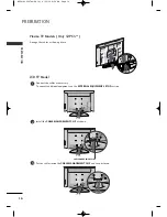
Page 15: ...he TV as shown Fix the 4 bolts securely using the holes in the back of the TV 1 2 3 G G When assembling the desk type stand check whether the bolt is fully tightened If not tightened fully the product can tilt forward after the product installation If you tighten the bolt with excessive force the bolt can deviate from abrasion of the tightening part of the bolt NOTE MFL41469207en Edit1 8 22 08 8 5...

Page 16: ...bolts securely using the holes in the back of the TV 4 S ST TA AN ND D B BO OD DY Y C CO OV VE ER R B BA AS SE E LCD TV Models Except 47LG30 G G When assembling the desk type stand check whether the bolt is fully tightened If not tightened fully the product can tilt forward after the product installation If you tighten the bolt with excessive force the bolt can deviate from abrasion of the tighten...

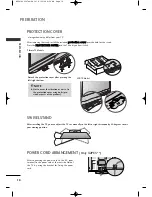
Page 17: ...be broken NOTE Connect the cables as necessary To connect additional equipment see the EXTERNAL EQUIPMENT SETUP section 1 Install the CABLE MANAGEMENT CLIP as shown If your TV has CABLE HOLDER fix it as shown and bundle the cables 2 How to remove the CABLE MANAGEMENT CLIP G G Hold the CABLE MANAGEMENT CLIP with both hands and pull it upward CABLE MANAGEMENT CLIP CABLE HOLDER 42PG20 50PG20 MFL41469...

Page 18: ...equipment see the EXTERNAL EQUIPMENT SETUP section Install the CABLE MANAGEMENT CLIP as shown CABLE MANAGEMENT CLIP 1 2 Put the cables inside the CABLE MANAGEMENT CLIP and snap it closed 3 Plasma TV Models Only 32PC5 Arrange the cables as shown picture MFL41469207en Edit1 8 22 08 8 54 AM Page 16 ...

Page 19: ...ten the product to the wall as shown in the picture If your product has the bolts in the eye bolts position before inserting the eye bolts loosen the bolts Secure the wall brackets with the bolts not provided as parts of the product must purchase separately to the wall Match the height of the bracket that is mounted on the wall to the holes in the product Ensure the eye bolts or brackets are tight...

Page 20: ... hole for the stand Press the P PR RO OT TE EC CT TI IO ON N C CO OV VE ER R into the TV until you hear it click Detech the protection cover after pressing the left right buttons Plasma TV Models NOTE G Not to occur the vibration or noise fix the protection cover using bolts pro vided as parts of the product POWER CORD ARRANGEMENT Only 32PC5 After connecting the power cord to the AC input terminal...

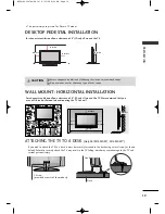
Page 21: ...to a desk it must be securely fastened to the desk using a metal screw as shown below Failure to securely attach the TV may result in the TV falling which may cause damage to the TV and serious personal injury 1 Screw provided as parts of the product Desk Stand DESKTOP PEDESTAL INSTALLATION For adequate ventilation allow a clearance of 4 10cm all around the TV 4 inches 4 inches 4 inches 4 inches G...

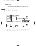
Page 22: ...door antenna Outdoor Antenna Wall Antenna Socket RF Coaxial Wire 75 ohm Antenna UHF VHF In poor signal areas to achieve better picture quality it may be necessary to install a signal amplifier to the antenna as shown above If signal needs to be split for two TVs use an antenna signal splitter for connection To prevent damage do not connect to the mains outlet until all connections are made between...

Page 23: ...I IN NP PU UT T button on the remote control If connected to C CO OM MP PO ON NE EN NT T I IN N2 2 select C Co om mp po on ne en nt t2 2 input source 2 3 4 1 To avoid damaging any equipment never plug in any power cords until you have finished connecting all equipment This section on EXTERNAL EQUIPMENT SETUP mainly uses diagrams for the Plasma TV models Image shown may differ from your TV Signal 4...

Page 24: ...720x480 720x576 1280x720 1920x1080i 1920x1080p HDMI DTV mode Horizontal Vertical Frequency kHz Frequency Hz 31 47 59 94 31 50 60 00 31 25 50 00 44 96 59 94 45 00 60 00 37 50 50 00 33 72 59 94 33 75 60 00 28 125 50 00 67 432 59 94 67 50 60 00 56 25 50 00 27 0 24 00 33 75 30 00 Plasma TV Models LCD TV Models Resolution 720x480 720x576 1280x720 1920x1080i 1920x1080p Horizontal Vertical Frequency kHz ...

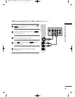
Page 25: ...Select H HD DM MI I1 1 D DV VI I input source using the I IN NP PU UT T button on the remote control 2 3 4 1 When connecting with a HDMI to DVI cable VIDEO AUDIO COMPONENT IN 1 2 RGB IN PC ANTENNA IN 1 2 AUDIO IN RGB DVI AV OUT AV IN VIDEO AUDIO COMPONENT IN 1 2 1 2 VIDEO VIDEO AUDIO COMPONENT COMPONENT IN IN 1 2 1 2 AUDIO IN AUDIO IN RGB DVI RGB DVI HDMI IN HDMI DVI IN HDMI IN HDMI DVI IN HDMI IN...

Page 26: ...s of the DVD to the C CO OM MP PO O N NE EN NT T I IN N A AU UD DI IO O jacks on the TV Turn on the DVD player insert a DVD Select C Co om mp po on ne en nt t1 1 input source using the I IN NP PU UT T button on the remote control If connected to C CO OM MP PO ON NE EN NT T I IN N2 2 select Component 2 input source Refer to the DVD player s manual for operating instructions 2 3 4 5 1 VIDEO AUDIO CO...

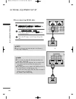
Page 27: ...t jacks on the TV Turn on the DVD player insert a DVD Select A AV V2 2 input source using the I IN NP PU UT T button on the remote control Refer to the DVD player s manual for operating instructions 2 3 4 5 1 HDMI IN HDMI DVI IN HDMI IN HDMI DVI IN 1 2 HDMI IN HDMI DVI IN AV IN 2 V IN 2 L R S VIDEO VIDEO OUTPUT SWITCH ANT IN ANT OUT L MONO R AUDIO VIDEO OUT VARIABLEAUDIO OUT 1 2 MFL41469207en Edit...

Page 28: ... T button on the remote control Refer to the DVD player s manual for operating instruc tions 1 G G The TV can receive video and audio signals simultaneously when using a HDMI cable NOTE 2 3 G G TV can receive the video and audio signal simultaneously with using a HDMI cable G G If the DVD supports Auto HDMI function the output resolu tion of the source device will be automatically set to 1280x720p...

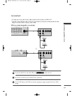
Page 29: ...visible Connect the ANT OUT socket of the VCR to the A AN NT TE EN NN NA A I IN N socket on the TV Connect the antenna cable to the ANT IN socket of the VCR Press the PLAY button on the VCR and match the appropriate program between the TV and VCR for viewing 1 2 2 3 1 or OUTPUT SWITCH ANT IN R S VIDEO VIDEO ANT OUT L VIDEO AUDIO COMPONENT IN ANTENNA IN 1 2 1 2 AV IN L MONO R AUDIO VIDEO ANTENNA AN...

Page 30: ...Left white and Audio Right red Insert a video tape into the VCR and press PLAY on the VCR Refer to the VCR owner s manual Select A AV V1 1 input source using the I IN NP PU UT T button on the remote control If connected to A AV V I IN N2 2 select A AV V2 2 input source 1 2 3 G G If you have a mono VCR connect the audio cable from the VCR to the A AU UD DI IO O L L M MO ON NO O jack of the TV NOTE ...

Page 31: ...onnect the S VIDEO output of the VCR to the S S V VI ID DE EO O input on the TV The picture quality is improved compared to normal composite RCA cable input Connect the audio outputs of the VCR to the A AU UD DI IO O input jacks on the TV Insert a video tape into the VCR and press PLAY on the VCR Refer to the VCR owner s manual Select A AV V2 2 input source using the I IN NP PU UT T button on the ...

Page 32: ...ect A AV V2 2 input source using the I IN NP PU UT T button on the remote control If connected to A AV V I IN N1 1 select A AV V1 1 input source Operate the corresponding external equipment Refer to external equipment operating guide 1 2 3 or L R VIDEO ANTENNA IN AV IN L MONO MONO R AUDIO AUDIO VIDEO VIDEO DIO IN RGB IN PC AUDIO IN RGB DVI AV OUT V OUT RS 232C IN CONTROL SERVICE VARIABLE ARIABLE A...

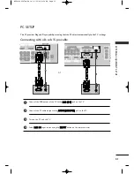
Page 33: ... cable Connect the RGB output of the PC to the R RG GB B P PC C jack on the TV Connect the PC audio output to the A AU UD DI IO O R RG GB B D DV VI I jack on the TV Turn on the PC and the TV Select R RG GB B P PC C input source using the I IN NP PU UT T button on the remote control 2 3 4 1 or RGB OUTPUT AUDIO VIDEO VIDEO AUDIO COMPONENT COMPONENT IN IN A ANTENNA IN 1 2 AV OUT V OUT AV IN L MONO AU...

Page 34: ...ies are separate G G If the resolution of PC is over SXGA there will be no picture on the TV Only HD Models G G Connect the audio cable from the PC to the Audio input on the TV Audio cables are not included with the TV G G If you use too long an RGB PC cable there may be interference on the screen We recommend using under 5m of the cable This provides the best picture quality NOTES Supported Displ...

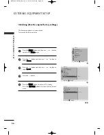
Page 35: ...N NU U button to return to TV viewing Press the R RE ET TU UR RN N button to move to the previous menu 2 1 4 5 3 6 Automatically adjusts picture position and minimizes image instability After adjustment if the image is still not cor rect your TV is functioning properly but needs further adjustment A Au ut to o c co on nf fi ig gu ur re e This function is for the automatic adjustment of the screen ...

Page 36: ... picture isn t clear after auto adjustment and especially if characters are still trembling adjust the picture phase manually It s not available to use Phase Clock function in COMPONENT 480i 480p 576i 576p 720p 1080i 1080p HDMI 480p 576p 720p 1080i 1080p C Cl lo oc ck k This function is to minimize any vertical bars or stripes visible on the screen background And the horizontal screen size will al...

Page 37: ...TU UR RN N button to move to the previous menu 2 1 4 5 3 To see a normal picture match the resolution of RGB mode and selection of XGA VGA mode This function works in the following mode RGB PC mode 1 Picture Mode Color Temperature Advanced Aspect Ratio Picture Reset Screen Picture DE F G RETURN 2 Picture Picture Mode Color Temperature Advanced Aspect Ratio Picture Reset Screen To Set Screen G DE F...

Page 38: ...ress the M ME EN NU U button to return to TV viewing Press the R RE ET TU UR RN N button to move to the previous menu 2 1 4 5 3 This function operates in current mode To initialize the adjusted value DE F G RETURN 1 Picture Mode Color Temperature Advanced Aspect Ratio Picture Reset Screen Picture DE F G RETURN 2 Picture Picture Mode Color Temperature Advanced Aspect Ratio Picture Reset Screen To S...

Page 39: ...ABLE AUDIO OUT G G When connecting with external audio equipments such as amplifiers or speakers please turn the TV speakers off G G Select V Va ar ri ia ab bl le e O Ou ut t in Audio manu to connect the V VA AR RI I A AB BL LE E A AU UD DI IO O O OU UT T jacks G G p p 7 76 6 NOTE Use to connected either an external amplifier or add a sub woofer to your surround sound system Connect the input jack...

Page 40: ... at the screen G G p p 5 52 2 POWER RATIO SOUND INPUT PICTURE Switches the TV on from standby or off to standby Change the aspect ratio G G p p 5 55 5 Select the appropriate type of sound for type of program G G p p 7 72 2 External input modes rotate in regular sequence Adjust the factory preset picture depend on the viewing environment G G p p 5 56 6 VOLUME UP DOWN FAV MUTE CH UP DOWN 0 9 number ...

Page 41: ...d set images and sounds when con necting AV devices G G p p 5 51 1 VCR DVD SIMPLINK Control buttons Control video cassette recorders or DVD players Control the SIMPLINK compatible devices Installing Batteries Open the battery compartment cover on the back and install the batteries matching cor rect polarity with with Install two 1 5V AAA batteries Do not mix old or used batteries with new ones Clo...

Page 42: ...Clear all on screen displays and return to TV viewing from any menu Select the desired quick menu source G G p p 4 43 3 Navigate the on screen menus and adjust the system set tings to your preference Allows the user to move return one step in an interactive application or other user interaction function It helps you select and set images and sounds when connecting AV devices G G p p 5 51 1 RATIO S...

Page 43: ...ty with with Install two 1 5V AAA batteries Do not mix old or used batteries with new ones Close cover 1 2 3 4 5 6 7 8 0 9 VOL CH ENTER POWER MUTE FAV RATIO Q VIEW PICTURE SOUND PIP INPUT MENU Q MENU RETURN AV MODE VOLUME UP DOWN FAV MUTE CH UP DOWN Increase decrease in the sound level Scroll through the programmed favorite channels G G p p 4 49 9 Switches the sound on or off G G p p 4 42 2 Select...

Page 44: ... button You can cancel the Mute function by pressing the M MU UT TE E or V VO OL L or button Adjust the volume to suit your personal preference 1 2 3 Initializing setup Note a It will automatically disappear after approx 40 seconds unless a button is pressed b In store mode is only for shop display and not for general customer use c Home mode is the optimal setting for home environments and is the...

Page 45: ...the sound output C Ca ap pt ti io on n T Te ex xt t Select a closed caption C Ch h M Me em mo or ry y E Er ra as se e Sets the channel add or delete S Slle ee ep p T Tiim me er r Select the amount of time before your TV turns off automatically Press the Q Q M ME EN NU U button and then or button to dis play each menu Press the or button to make appropriate adjustments Press the Q Q M ME EN NU U bu...

Page 46: ... button You can move to a higher level menu by pressing the E EN NT TE ER R or M ME EN NU U button 1 2 3 Plasma TV model LCD TV model Setup MENU Picture MENU Audio MENU Time MENU Option MENU Language SIMPLINK Key Lock Caption Text ISM Method Power Saving Set ID Factory Reset Option Clock Off Time On Time Sleep Timer Auto Sleep Time Auto Tuning Manual Tuning Favorite Channel Setup Sound Mode Auto V...

Page 47: ...e active chan nels in your area before you are able to use the TV There are two ways of storing channels in the TV s memory You can use either One is called Auto Tuning and the other is called Manual Tuning In Auto Tuning mode the TV will memorize the channels in ascending numerical order If there are additional channels you want to add or delete you can manually add or delete those channels with ...

Page 48: ...CATV 39 Memory On Fine 0 Booster Off Manual Tuning DE F G RETURN Memory Press the M ME EN NU U button and then or button to select the S Se et tu up p menu Press the button and then or button to select M Ma an nu ua al l T Tu un ni in ng g Press the button and then or button to select c ch ha an nn ne el l n nu um mb be er r Press the button and then or button to select M Me em mo or ry y or E Er ...

Page 49: ...i in ne e Press the or button to adjust the picture to your preference Press the M ME EN NU U button to return to TV viewing Press the R RE ET TU UR RN N button to move to the previous menu 2 1 4 5 3 1 2 Setup Auto Tuning Manual Tuning Favorite Channel CATV 39 Memory Fine 0 Booster Off Manual Tuning G DE F G RETURN Auto Tuning Manual Tuning Favorite Channel Setup DE F G RETURN Setup Auto Tuning Ma...

Page 50: ... an nu ua al l T Tu un ni in ng g Press the button and then use or button to select B Bo oo os st te er r Press the or button to O On n or O Of ff f Press the M ME EN NU U button to return to TV viewing Press the R RE ET TU UR RN N button to move to the previous menu 2 1 4 5 3 1 2 Setup Auto Tuning Manual Tuning Favorite Channel CATV 39 Memory Fine 0 Booster Off Manual Tuning G DE F G RETURN Auto ...

Page 51: ...the button and then use or button to select the first favorite channel position Press the or button to set the desired channel number for first favorite channel Repeat steps 3 to 5 to memorize other favorite chan nels You can store up to 8 channels Press the M ME EN NU U button to return to TV viewing Press the R RE ET TU UR RN N button to move to the previous menu 2 3 4 5 6 1 2 3 4 1 Setup Auto T...

Page 52: ...he R RE ET TU UR RN N button to move to the previous menu 2 3 4 1 1 3 2 Option Language SIMPLINK Key Lock Caption Text ISM Method Power Saving Set ID Power Indicator Factory Reset Key Lock G DE F G RETURN Off On Language SIMPLINK Key Lock Caption Text ISM Method Power Saving Set ID Power Indicator Factory Reset Option DE F G RETURN NOTE G G In K Ke ey y L Lo oc ck k O On n if the TV is turned off ...

Page 53: ...pectively If you select Off in AV mode the picture and image which you initially set will be selected Press the R RE ET TU UR RN N button to return to normal TV viewing 1 2 As pressing the AV MODE button to change the Cinema Sport and Game at the same time you can see the optimal images and sounds It gives the viewing environment Picture Quality Sound Quality optimized for the consumers Off Cinema...

Page 54: ...f Press the M ME EN NU U button to return to normal TV viewing Press the R RE ET TU UR RN N button to move to the previous menu screen 2 3 4 1 1 3 2 Option Language SIMPLINK Key Lock Caption Text ISM Method Power Saving Set ID Power Indicator Factory Reset SIMPLINK G DE F G RETURN Off On Language SIMPLINK Key Lock Caption Text ISM Method Power Saving Set ID Power Indicator Factory Reset Option DE ...

Page 55: ...should be used SimpLink Functions SimpLink Menu Press the S SI IM MP PL LI IN NK K button Use button to select the desired device and then press the E EN NT TE ER R button Control connected AV devices by pressing the G A l l l l FF GG E EN NT TE ER R buttons 2 1 3 T TV V v vi ie ew wi in ng g Switch to the previous TV programme regardless of the current mode D DI IS SC C p pl la ay yb ba ac ck k S...

Page 56: ...ts sources on your TV screen at the same time One source will be large and the other source will show a smaller inset image PIP function is available in the Component RGB HDMI mode For FHD models it can support TV AV1 AV2 mode Channel Selection for Sub Picture Press the P PI IP P button and then press the button to select a channel for the sub picture The selected channel number is displayed just ...

Page 57: ...following selection will allow you to view the picture without any alteration while filling the entire screen However the top and bot tom of the picture will be cropped You can adjust the enlarge proportion using or button Z Zo oo om m2 2 Choose Zoom 2 when you wish the picture to be altered both horizontally extended and vertically cropped The picture adopting a compromise between alteration and ...

Page 58: ...NU U button and then or button to select the P Pi ic ct tu ur re e menu Press the button and then or button to select P Pi ic ct tu ur re e M Mo od de e Press the button and then or button to select I In nt te el ll li ig ge en nt t S Se en ns so or r Only 32 42LG50 V Vi iv vi id d S St ta an nd da ar rd d C Ci in ne em ma a S Sp po or rt t G Ga am me e U Us se er r1 1 or U Us se er r2 2 Press the...

Page 59: ...en or button to select C Co ol lo or r T Te em mp pe er ra at tu ur re e Press the button and then or button to select either C Co oo ol l M Me ed di iu um m or W Wa ar rm m Press the M ME EN NU U button to return to TV viewing Press the R RE ET TU UR RN N button to move to the previous menu screen 1 2 3 4 Auto Color Tone Control Cool Medium Warm 1 3 2 Picture Mode Color Temperature Advanced Aspec...

Page 60: ... adjust the bright ness of LCD panel Only LCD TV models C Co on nt tr ra as st t Adjusts the difference between light and dark B Br ri ig gh ht tn ne es ss s Increases or decreases the amount of white in the picture C Co ol lo or r Adjusts intensity of all colors S Sh ha ar rp pn ne es ss s Adjusts the level of crispness in the edges between the light and dark areas of the picture The lower the le...

Page 61: ... and then or button to select U Us se er r Press the button and then or button to select R Re ed d G Gr re ee en n or B Bl lu ue e Press the or button to make appropriate adjustments Press the M ME EN NU U button to return to TV viewing Press the R RE ET TU UR RN N button to move to the previous menu screen 1 2 3 4 5 6 1 3 2 4 Picture Mode Color Temperature Advanced Aspect Ratio Picture Reset Scre...

Page 62: ... Press the R RE ET TU UR RN N button to move to the previous menu screen XD is LG electronic s unique picture improving technology to display a real HD source through an advanced digital signal processing algorithm It is not possible to use this function in RGB PC mode 1 2 3 4 1 3 2 Picture Mode Color Temperature Advanced Aspect Ratio Picture Reset Screen Picture DE F G RETURN Picture Picture Mode...

Page 63: ...atically to reproduce as closely as possible to the natural colors X XD D N NR R Removing the noise up to the point where it does not damage the original picture Press the button and then or button to select O Of ff f L Lo ow w or H Hi ig gh h XD Contrast O Of ff f L Lo ow w or H Hi ig gh h XD Color O Of ff f L Lo ow w H Hi ig gh h or A Ad da ap pt ti iv ve e XD NR Press the M ME EN NU U button to...

Page 64: ... select G Ga am mm ma a Press the button and then or button to select L Lo ow w M Me ed di iu um m or H Hi ig gh h Press the M ME EN NU U button to return to TV viewing Press the R RE ET TU UR RN N button to move to the previous menu screen 1 2 3 4 5 1 3 2 4 Picture Mode Color Temperature Advanced Aspect Ratio Picture Reset Screen Picture DE F G RETURN Picture Picture Mode Color Temperature Advanc...

Page 65: ... to select F Fi il lm m M Mo od de e Press the button and then or button to select O On n or O Of ff f Press the M ME EN NU U button to return to TV viewing Press the R RE ET TU UR RN N button to move to the previous menu screen 1 2 3 4 5 1 3 2 4 Picture Mode Color Temperature Advanced Aspect Ratio Picture Reset Screen Picture DE F G RETURN Picture Picture Mode Color Temperature Advanced Aspect Ra...

Page 66: ...l Press the button and then or button to select L Lo ow w or H Hi ig gh h A A L Lo ow w The reflection of the screen gets darker A A H Hi ig gh h The reflection of the screen gets brighter Press the M ME EN NU U button to return to TV viewing Press the R RE ET TU UR RN N button to move to the previous menu screen 1 2 3 4 5 1 3 2 4 Picture Mode Color Temperature Advanced Aspect Ratio Picture Reset ...

Page 67: ...utton to select A Ad dv va an nc ce ed d Press the button and then or button to select E Ey ye e C Ca ar re e Press the button and then or button to select O Of ff f or O On n Press the M ME EN NU U button to return to TV viewing Press the R RE ET TU UR RN N button to move to the previous menu screen 1 2 3 4 5 1 3 2 4 Picture Mode Color Temperature Advanced Aspect Ratio Picture Reset Screen Pictur...

Page 68: ... ME EN NU U button to return to TV viewing Press the R RE ET TU UR RN N button to move to the previous menu screen Returns to the default factory setting for Picture Mode Color Temperature XD Advanced Aspect Ratio 1 2 3 4 1 3 2 Picture Mode Color Temperature Advanced Aspect Ratio Picture Reset Screen Picture DE F G RETURN Picture Picture Mode Color Temperature Advanced Aspect Ratio Picture Reset S...

Page 69: ...N Standby Light Power Light Standby Light G DE F G RETURN Power Indicator Off On 4 Press the M ME EN NU U button and then or button to select the O Op pt ti io on n menu Press the button and then or button to select P Po ow we er r I In nd di ic ca at to or r Press the button to select S St ta an nd db by y L Li ig gh ht t or P Po ow we er r L Li ig gh ht t Press the button and then or button to s...

Page 70: ...he image Avoid allowing a fixed image to remain on the screen for prolonged periods W Wh hi it te e W Wa as sh h White wash removes permanent images from the screen Note An excessive permanent image may be impossible to clear entirely with White Wash O Or rb bi it te er r Orbiter may help prevent ghost images However it is best not to allow any fixed image to remain on the screen To avoid a perman...

Page 71: ...he button and then or button to select O On n or O Of ff f Only 32PC5 Press the M ME EN NU U button to return to TV viewing Press the R RE ET TU UR RN N button to move to the previous menu screen 1 2 3 4 1 3 2 Option Language SIMPLINK Key Lock Caption Text ISM Method Power Saving Set ID Power Indicator Factory Reset Power Saving G DE F G RETURN Level 0 Level 1 Level 2 Level 3 Level 4 Language SIMP...

Page 72: ...ss the button and then or button to select Y YE ES S or N NO O Press the M ME EN NU U button to return to TV viewing Press the R RE ET TU UR RN N button to move to the previous menu screen 1 2 3 4 1 3 2 Option Language SIMPLINK Key Lock Caption Text ISM Method Power Saving Set ID Power Indicator Factory Reset Factory Reset G DE F G RETURN Language SIMPLINK Key Lock Caption Text ISM Method Power Sa...

Page 73: ...Of ff f Press the M ME EN NU U button to return to TV viewing Press the R RE ET TU UR RN N button to move to the previous menu screen Auto Volume automatically remains on the same level of volume if you change programs 1 2 3 4 1 Sound Mode Auto Volume Balance 0 TV Speaker Audio Out Audio 3 2 Audio Sound Mode Auto Volume Balance 0 TV Speaker Audio Out Auto Volume G DE F G RETURN Off On DE F G RETUR...

Page 74: ...s the M ME EN NU U button and then or button to select the A Au ud di io o menu Press the button and then or button to select S So ou un nd d M Mo od de e Press the button and then or button to select S SR RS S T TS SX XT T C Cl le ea ar r V Vo oi ic ce e S St ta an nd da ar rd d M Mu us si ic c C Ci in ne em ma a S Sp po or rt t G Ga am me e or U Us se er r Press the M ME EN NU U button to return...

Page 75: ...r button Set the desired sound level with the or button Press the M ME EN NU U button to return to TV viewing Press the R RE ET TU UR RN N button to move to the previous menu screen Adjusting the audio equalizer 1 2 3 4 5 6 1 3 4 2 Sound Mode Auto Volume Balance 0 TV Speaker Audio Out Audio Audio Sound Mode Auto Volume Balance 0 TV Speaker Audio Out Sound Mode G DE F G RETURN SRS TSXT Clear Voice ...

Page 76: ...button to select B Ba al la an nc ce e Press the button and then or button to make desired adjustment Press the M ME EN NU U button to return to TV viewing Press the R RE ET TU UR RN N button to move to the previous menu screen 1 2 3 4 1 3 2 Sound Mode Auto Volume Balance 0 TV Speaker Audio Out Audio DE F G RETURN Audio Sound Mode Auto Volume Balance 0 TV Speaker Audio Out Balance R15 DE F G RETUR...

Page 77: ...button to select the A Au ud di io o menu Press the button and then or button to select T TV V S Sp pe ea ak ke er r Press the button and then or button to select O On n or O Of ff f Press the M ME EN NU U button to return to TV viewing Press the R RE ET TU UR RN N button to move to the previous menu screen 1 2 3 4 1 2 3 Sound Mode Auto Volume Balance 0 TV Speaker Audio Out Audio DE F G RETURN Aud...

Page 78: ... 1 2 3 4 1 2 3 Sound Mode Auto Volume Balance 0 TV Speaker Audio Out Audio DE F G RETURN Audio Sound Mode Auto Volume Balance 0 TV Speaker Audio Out Audio Out G DE F G RETURN Monitor Out Variable Out ON SCREEN MENUS LANGUAGE SELECTION The menus can be shown on the screen in the selected language First select your language Press the M ME EN NU U button and then use or button to select the O Op pt t...

Page 79: ...ignal with the captions while another mode might show demonstration or programming information Your TV might not receive caption signals normally in the following situations I IG GN NI IT TI IO ON N Picture may flutter drift suffer from black spots or horizontal streaking Usually caused by interference from automobile ignition systems neon lamps electrical drills and other electrical appliances G ...

Page 80: ...e Press the M ME EN NU U button to return to TV viewing Press the R RE ET TU UR RN N button to move to the previous menu screen You must set the time correctly before using on off timer function If current time setting is erased by a power failure or the TV is unplugged reset the clock 1 2 3 4 5 1 3 4 2 Time Clock Off Time On Time Sleep Timer Auto Sleep Clock G DE F G RETURN AM Clock Off Time On T...

Page 81: ... menu screen The Off time function automatically switches the TV to standby at a preset time Two hours after the TV is switched on by the on time function it will auto matically switch back to standby mode unless a button has been pressed Once the on time off time is set these functions operate daily at the preset time The Off time function overrides the On time function if both are set to the sam...

Page 82: ... and then or button to select the T Ti im me e menu Press the button and then or button to select S Sl le ee ep p T Ti im me er r Press the button and then or button to set the minute Press the M ME EN NU U button to return to TV viewing Press the R RE ET TU UR RN N button to move to the previous menu screen 1 2 3 4 1 4 3 2 Time Clock Off Time On Time Sleep Timer Auto Sleep Sleep Timer G DE F G RE...

Page 83: ...en or button to select A Au ut to o S Sl le ee ep p Press the button and then or button to select O On n or O Of ff f Press the M ME EN NU U button to return to TV viewing Press the R RE ET TU UR RN N button to move to the previous menu screen 1 2 3 4 1 3 2 Time Clock Off Time On Time Sleep Timer Auto Sleep Auto Sleep G DE F G RETURN Clock Off Time On Time Sleep Timer Auto Sleep Time DE F G RETURN...

Page 84: ...a ap pp pe ea ar rs s s sl lo ow w l ly y a af ft te er r s sw wi it tc ch hi in ng g o on n Check whether the TV is switched on Try another channel The problem may be with the broadcast Is the power cord inserted correctly into the mains Check your antenna direction and or location Test the mains outlet by plugging another TV into the same outlet This is normal the image is muted during the TV st...

Page 85: ...screen Ensure there is no excess water on the screen Allow any water or dampness to evaporate before switching on Cleaning the Cabinet To remove dirt or dust wipe the cabinet with a soft dry lint free cloth Do not to use a wet cloth Extended Absence G G If you expect to leave your TV dormant for prolonged periods such as a holiday unplug the power cord to protect against possible damage from light...

Page 86: ...25 75 ohm 32 104 F 0 40 C Less than 80 4 140 F 20 60 C Less than 85 48 2 x 33 4 x 14 3 inches 1224 7 x 849 0 x 364 0 mm 48 2 x 31 1 x 3 3 inches 1224 7 x 790 0 x 86 0 mm 92 1 pounds 41 8kg 83 3 pounds 37 8 kg Power requirement Television System Program Coverage External Antenna Impedance Operating Temperature Range Operating Humidity Range Storage Temperature Range Storage Humidity Range 40 9 x 28...

Page 87: ...es 801 8 x 544 1 x 79 0 mm 29 5 pounds 13 4 kg 26 2 pounds 1 1 9 kg Power requirement Television System Program Coverage External Antenna Impedance Operating Temperature Range Operating Humidity Range Storage Temperature Range Storage Humidity Range 42LG30R 42LG30R MA 40 6 x 29 2 x 1 1 5 inches 1032 8 x 742 3 x 293 8 mm 40 6 x 26 3 x 3 6 inches 1032 8 x 670 1 x 92 0 mm 52 0 pounds 23 6 kg 46 2 pou...

Page 88: ...button such as a D DV VD D or or S ST TB B on the remote control The remote control button of the desired device is illumintated Press the M ME EN NU U and M MU UT TE E buttons simultaneously the remote control is ready to be programmed with the code Enter a code number using the number buttons on the remote control Programming code numbers for the corresponding component can be found on the follo...

Page 89: ...094 095 096 097 098 099 100 122 ELECTRO HOME 089 EUROPLUS 1 14 FUJITSU 017 021 022 027 133 134 GENERAL INSTRUMENT 003 004 016 029 031 059 101 HITACHI 139 140 HOUSTON TRACKER 033 037 039 051 057 104 HUGHES 068 Humax SL 158 JANIEL 060 147 JERROLD 061 KATHREIN 108 LEGEND 057 LG 001 LUTRON 132 LUXOR 062 144 MACOM 010 059 063 064 065 MEMOREX 057 NEXTWAVE 028 124 125 NORSAT 069 070 PACE SKY SATELLITE 14...

Page 90: ...D2 D3 D4 D5 D6 D7 D0 D1 D2 D3 D4 D5 D6 D7 Lead code Low custom code High custom code Data code Data code Repeat code Tf 4 5 ms 9 ms 2 25 ms 9 ms 0 55 ms 0 56 ms 1 12 ms 0 56 ms 2 24 ms Tf Tf Tf 108ms 455KHz Bit 0 Bit 1 1 How to Connect A Connect your wired remote control to the Remote Control port on the TV 2 Remote Control IR Codes A Output waveform Single pulse modulated with 37 917KHz signal at...

Page 91: ...ton 03 VOL R C Button 00 CH R C Button 01 CH R C Button 30 AV MODE R C Button 09 MUTE R C Button 10 19 Number Key 0 9 R C Button 1E FAV R C Button 1A Q VIEW R C Button 7E SIMPLINK R C Button B1 A Stop R C Button B0 G Play R C Button BA l l l lPause R C Button 8F FF Rew R C Button 8E GG FF R C Button 45 Q MENU R C Button BD Ô Record R C Button 52 SOUND R C Button 4D PICTURE R C Button 79 RATIO R C ...

Page 92: ...to the RS 232C jack on the TV back panel RS 232C con nection cables are not supplied with the TV AUDIO RGB DVI RGB PC RGB IN RS 232C IN CONTROL L MONO R AUDIO VIDEO VIDEO L R AUDIO HDMI IN HDMI IN HDMI DVI IN HDMI DVI IN Type of Connector D Sub 9 Pin Male No Pin Name 1 No connection 2 RXD Receive data 3 TXD Transmit data 4 DTR DTE side ready 5 GND 6 DSR DCE side ready 7 RTS Ready to send 8 CTS Cle...

Page 93: ...p pt ti io on n menu Press the button and then use or button to select S Se et t I ID D Press the button and then use or button to adjust S Se et t I ID D to choose the desired TV ID number The adjustment range of SET ID is 1 99 Press the M ME EN NU U button to return to TV viewing Press the R RE ET TU UR RN N button to move to the previous menu screen Use this function to specify a set ID number ...

Page 94: ...just the set ID to choose desired TV ID number in Setup menu Adjustment range is 1 99 When selecting Set ID 0 every connected TV is controlled Set ID is indicated as decimal 1 99 on menu and as Hexa decimal 0x0 0x63 on transmission receiving protocol DATA To transmit command data Transmit FF data to read status of comand Cr Carriage Return ASCII code 0x0D ASCII code space 0x20 O OK K A Ac ck kn no...

Page 95: ...an nd d k k e e To control volume mute on off You can also adjust mute using the MUTE button on remote control Data 00 Volume mute on Volume off Data 01 Volume mute off Volume on Transmission k e Set ID Data Cr Acknowledgement e Set ID OK NG Data x 0 05 5 V Vo ollu um me e C Co on nt tr ro oll C Co om mm ma an nd d k k f f To adjust volume You can also adjust volume with the volume buttons on remo...

Page 96: ...K NG Data x 1 15 5 B Ba alla an nc ce e C Co om mm ma an nd d k k t t To adjust balance You can also adjust balance in the Audio menu Data Min 00 Max 64 Refer to Real data mapping 1 See page 95 Transmission k t Set ID Data Cr Acknowledgement t Set ID OK NG Data x 1 10 0 S Sh ha ar rp pn ne es ss s C Co om mm ma an nd d k k k k To adjust the screen sharpness You can also adjust sharpness in the Pic...

Page 97: ...x 2 23 3 A Au ut to o C Co on nf fiig gu ur re e C Co om mm ma an nd d jj u u To adjust picture position and minimize image shaking automatically It works only in RGB PC mode Data 01 To set Transmission j u Set ID Data Cr Acknowledgement u Set ID OK NG Data x R Re ea al l d da at ta a m ma ap pp pi in ng g 1 1 00 Step 0 A Step 10 F Step 15 10 Step 16 64 Step 100 6E Step 1 10 73 Step 1 15 74 Step 1...

Page 98: ...0 3 0 0 4 x x Reserved 5 0 1 Use No Use Using Physical Channel 6 0 1 Two One Two One Part Channel 7 0 1 Main Sub Main Sub Picture 0 0 1 T Tw wo o O On ne e p pa ar rt t C Ch ha an nn ne el l 6 6t th h b bi it t This bit is used in a cable ready system U Us si in ng g p ph hy ys si ic ca al l c ch ha an nn ne el l 5 5t th h b bi it t If the channel band is NTSC air or NTSC cable channel tuning can ...

Page 99: ...ement b Set ID OK NG Data x 2 28 8 I In np pu ut t s se elle ec ct t C Co om mm ma an nd d x x b b M Ma aiin n P Piic ct tu ur re e I In np pu ut t To select input source for TV Data Structure Transmission x b Set ID Data Cr Input Number Data 0 0 0 0 Input1 0 0 1 1 Input4 0 0 1 0 Input3 0 0 0 1 Input2 MSB LSB 0 0 0 0 0 0 0 0 External Input Input Number 3 30 0 C Co on nt tr ro oll B Ba ac ck klliig...

Page 100: ...MFL41469207en Edit2 8 22 08 8 55 AM Page 98 ...

Reviews: