- 10 -
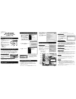
8. SUB-BRIGHTNESS Adjustment
Prior to this adjustment, the White balance adjustment
should be finished.
8-1. Adjustment Preparation
1) Receive the PAL B/G 5CH signal into RF mode
regardless of channel.
2) Set the PSM condition to “DYNAMIC”.
8-2. Adjustment
1) Select SUB-BRIGHT Adjustment Mode by pressing ADJ.
key on the SVC Remote control
2) At the point of becoming equal in left 2 boundaries are
located in lower Gray Scale of PAL B/G 05CH signal,
adjustment is completed by pressing the VOL
F
, VOL
G
key on the remote control.
9. Deflection setting data adjustment
This adjustment must be done by automatic adjustment
Equipment.
In case of manual adjustment, Adjustment will be done as
follows.
9-1. Adjustment Preparation
1) Set the Deflection data with the SVC Remote control.
2) Select the Deflection adjustment mode by pressing IN-
START key.
3) Use the CH
D
, CH
E
key to select adjustment item.
4) Use the VOL
F
, VOL
G
key for data changing
9-2. Adjustment
1) Horizontal Position Adjustment
Select VP1(H-POS) and adjust until left and right screen
are symmetrically equal.
2) Vertical Position Adjustment
Select VP2(V-POS) and adjust until the mechanical center
point and the center of screen unite
3) Vertical Size Adjustment
Select VP3(V-SIZE) and adjust until the smaller inscribed
circle of Digital Pattern coincides with the outer frame of
screen as figure below.
10. IIC BUS Adjustment Data Table
: Refer to <TABLE 1>
11. Instrument setting data
(automatic adjustment)
<TABLE 2>
12. EEPROM OPTION TABLE
<TABLE 3>
OPTION 1
DVD
TURBO ME
V-CURVE
V-MUTE
EYE
FLAT
SND MUTE
GAME
OPTION2
TURBO
ARC
200PR
BLUEBACK
TURBO AT
HOTEL
SHARP
DVDN
OPTION3
FM TRANS
FM HIGH
NTSC
AV PSEU
SYNC KI
A2 SW
LNA
SWOOFER
OPTION 4
SYSTEM
SND MODE
AV
LOC KEY
COLOR T
PLL DIV
MTS LEV
OPTION 5
FM PRE
NICAM PRE
SCART PRE
A2 FM TH
FIRST TH
ZWT TH
INITIAL
0
0
0
0
0
1
1
0
0
0
0
1
1
0
0
1
0
0
1
1
1
0
0
0
4
1
2
1
1
31
22
6
13
0
5
15
2
REMARK
DVD function (1:Yes, 0:No)
T-P,T-S function in MENU (Display or not)
VOLUME CURVE (1:HIGH, 0:LOW)
VIDEO MUTE
EYE function (1:Yes, 0:No)
CPT SECTION
SOUND MUTE at no signal (yes or not)
GAME function (1:Yes, 0:No)
REMARK
TURBO P/S function (1:Yes, 0:No)
ARC function (1:Yes, 0:No)
Number of CH. MEMORY : 200
BLUEBACK display (1:Yes, 0:No)
TURBO SEARCH function (1:Yes, 0:No)
HOTEL function (1:Yes, 0:No)
SHARPNESS DATA (1:+10, 0:NORMAL)
DVD SOUND -> AV (1:possibility, 0:impossibility)
REMARK
FM TRANS function (1:Yes, 0:No)
FM TRANS FREQUENCY (1:HIGH, 0:LOW)
NTSC function (1:Yes, 0:No)
AV ST MODE (1:PSEUDO, 0:MATRIX)
SYNC KILL function (1:Yes, 0:No)
MONO DUAL function (1:5.74MHz possible, 0:NORMAL)
LNA TUNER (1:LNA, 0:NORMAL)
WOOFER function (1:Yes, 0:No)
REMARK
0:CHINA / 1:INDONESIA / 2:THAI / 3:VIETNAM / 4:MULTI
0:MONO / 1:AV ST / 2:REAL ST
0:NO AV / 1:AV1 / 2:AV1,2 / 3:AV1,2,3
0:4KEY / 1:6KEY / 2:8KEY
COLOR TABLE
PLL DATA (NTSC Tuning Level)
STEREO LEVEL
REMARK
FM PRESCALER
NICAM PRESCALER
SCART PRESCALER
A2 PRESCALER
MONO THRESHOLD
A2 THRESHOLD
Speed
1
SLave ADD
VIDEO IC
BA
EEPROM
A2
Delay
30
EEPROM
Sub Add
74
71
76
73
SpeedPlus
Step/Data
3
3
3
3
Sub Add
Start Bit
Stop Bit
Masking
Direction
VCD
TV
PC
B(R)AMP
C
6
0
0
1
B(R)CUT
9
7
0
0
1
G(B)AMP
E
6
0
0
1
G(B)CUT
B
7
0
0
1
B AMP
B CUT
G AMP
G CUT
At the same point
of brightness
<Fig. 4>
Summary of Contents for 21FJ4AB/RB
Page 15: ... 13 PRINTED CIRCUIT BOARD MAIN ...
Page 17: ... 15 4 SMPS PRIMARY SECTION 5 SMPS SECONDARY SECTION ...
Page 18: ... 16 6 VERTICAL SECTION 7 HORIZONTAL SECTION ...
Page 19: ...8 SOUND PROCESSING SECTION 17 9 CPT DRIVE SECTION ...
Page 20: ... 18 BLOCK DIAGRAM HIC291 ...
Page 21: ... 19 MEMO ...
Page 22: ... 20 EXPLODED VIEW 300 330 320 310 120 504 520 112 150 170 913 153 Option 400 943 174 ...
Page 28: ...P NO 3854VA0196B S1 2005 8 16 ...
Page 29: ...SVC SHEET 3854VA0196B S ...


