ARIA SOHO Hardware Description and Installation Manual
Issue 1
BOARD INSTALLATION
Aug, 2006
32
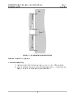
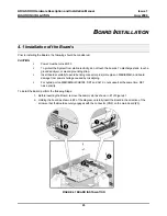
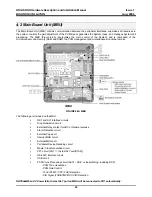
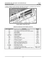
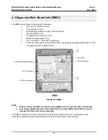
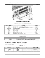
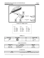
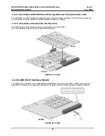
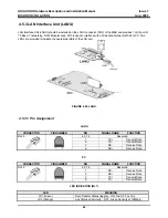
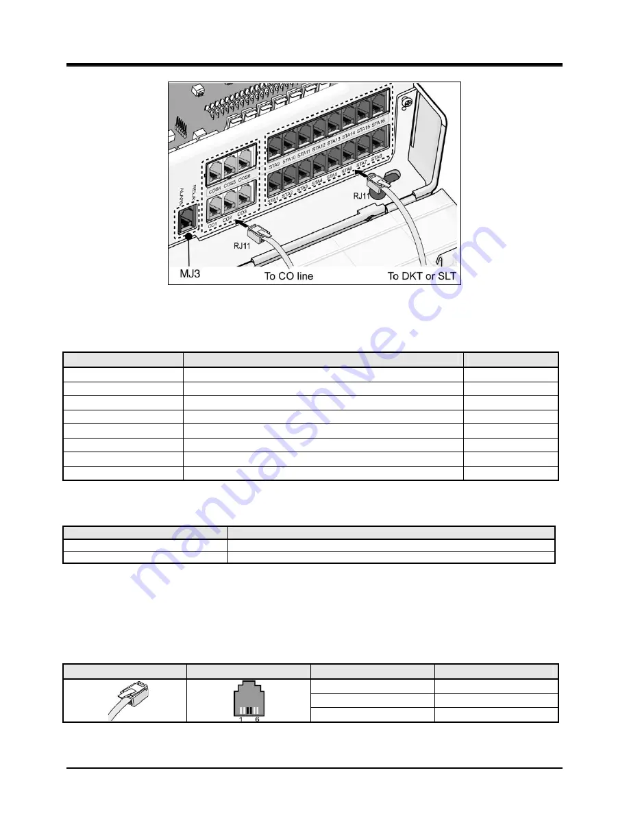
FIGURE 4.3B EMBU CONNECTION PORTS
CONNECTOR/MODULAR JACK/SWITCH FUNCTIONS
SWITCH/CONNECTOR
FUNCTIONS
REMARK
CN1
KSU Connection from Basic KSU with Flat cable
50Pins
CN2
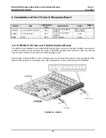
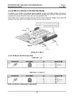
CO and Extension board (CHB308, CSB316, SLIB8) installation
50Pins
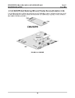
CN9 & CN10
CMU50PR installation
6 & 8 Pins
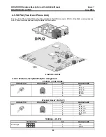
CN13
DPU2 installation
16 Pins
CN7 PSU
connection
7Pins
MJ1
3 CO connection
3 Arrays
MJ2
8 DKTs or 8SLTs connection
8 Arrays
MJ3
Alarm Sensor and External Relay contact
1 Array
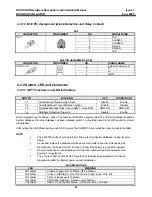
LED INDICATIONS
LED
MEANING
LD1 (Blue)
Power Status – LED ON : Power on; LED OFF : Power OFF
LD2 (Blue)
In Use or Idle State – ON, One or more ports in use; OFF, Idle
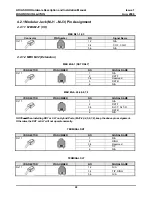
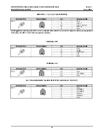
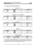
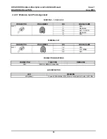
4.3.1 Modular Jack (MJ1 – MJ3) Pin Assignment
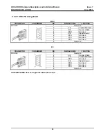
4.3.1.1 EMBU MJ1(CO)
EMBU MJ1 – 1,2,3
CONNECTOR
PIN NUMBER
NO
SIGNAL NAME
1,2 N/A
3,4 CO-T,
CO-R
RJ11
5,6 N/A


