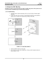
ARIA SOHO Hardware Description and Installation Manual
Issue 1
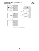
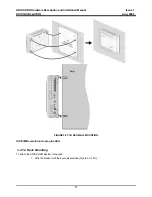
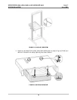
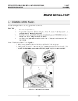
BOARD INSTALLATION
Aug, 2006
26
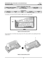
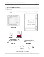
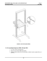
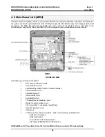
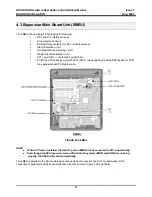
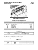
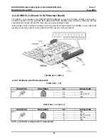
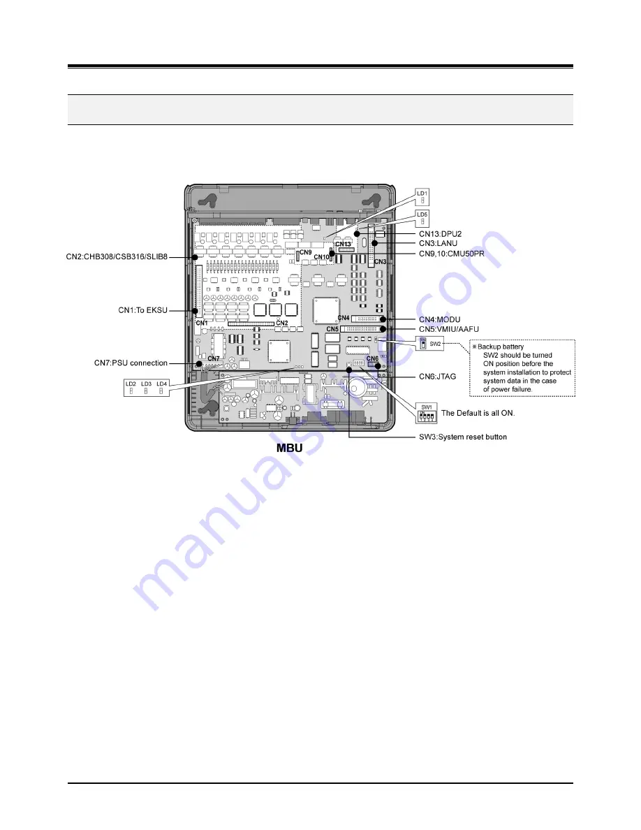
4.2 Main Board Unit (MBU)
The Main Board Unit (MBU) controls communication between the peripheral interfaces, supervises all resources in
the system, controls the gain adjustment of the PCM signal, generates the System tones, and manages System call
processing. The MBU (Figure 4.2A) incorporates the main control of the System, and is composed of the
microprocessor and memory (RAM and ROM), the PCM management and miscellaneous functional circuits.
FIGURE 4.2A MBU
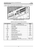
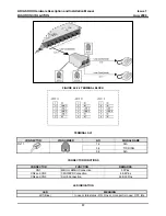
The following are included on the MBU:
DKT and SLT interface circuits
Ring Generation circuit
External Relay contact for LBC or General purpose
Alarm Detection circuit
External Page port
Internal MOH circuit
External MOH port
Peripheral Device Decoding circuit
Master Clock Generation circuit
PFT circuit [CO1 the last SLT port(STA8)]
RS-232C Interface circuit
USB circuit
PCM Voice Processing circuit (ACT2 - ASIC, voice switching, including DSP)
- PCM Tone Generation
- PCM Gain Control
- Tone (DTMF / CPT / FAX) Detection
- CID Signal (FSK/DTMF/RUS CID) Detection
NOTE
ㅡ
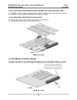
When AC Power fails, the last SLT port on MBU will be connected to CO1 automatically.


