background image

7. Additional Relay 

Summary of Contents for SafezoneXID-500

Page 1: ...SafezoneXID 500 Instruction Guide Ver 0 3 ...

Page 2: ...ve the IP 65 test certification Do not drop the terminal or subject it to heavy impact Do not apply heavy pressure to the touch screen Do not disassemble repair or reconstruct the terminal Do not use the terminal for any other purpose than original use In cases of product malfunction or problems please contact a provider Keep the product out of reach from people without authority The Following ins...

Page 3: ...1 Port ...

Page 4: ...T2 is indicating DOORSTATUS signal 3 INPUT3 Optional Input OUTPUT port 1 Electrical Lock connection LOCK NO NO connection LOCK NC NC connection COM COM connection 2 LOCK TR for external Relay optional Power Connection RS 485 RS 485 GND RS 232 RXD WIEGAND RS 232 TXD WIEGAND INPUT1 GND INPUT1 INPUT2 GND INPUT2 INPUT3 GND INPUT3 LOCK NO COM LOCK NC LOCK TR LOCK TR LAN POWER 485 232 INPUT OUTPUT DIP S...

Page 5: ...voltage level if it is 12V Since including Adaptor have FGND so that Installer should check FGND with Adaptor 2 RS232 WIEGAND Dip switch install RS232 Set as 2 3 and 5 6 WIEGAND Set as 1 2 and 4 5 3 LOCK Control In case of emergency status like blackout or power failure Operator can use NC or NO ...

Page 6: ...2 Network Setting ...

Page 7: ...nnection of hook Prevent the substance in the RJ 45 The following Icon indicates the network condition Link down please check the cable connection Link up physical connection is ok but need to check the setting such like IP Link up and activation of data are OK ...

Page 8: ...3 EM Deadbolt Strike One direction Installation ...

Page 9: ... NC AWG24 2C 문상태 문상태GND Connection Set UTP cable 1 PCS Power Line 2P Control Line 6P Including LOCK NC LOCK COM Door status 2 cores Exit 2 cores Electrical Lock should have the sensor of the door status AWG24 2C on off signal AWG24 2C AWG24 1C LOCK COM AWG24 1C power Power Power GND Power GND ...

Page 10: ...3 EM Deadbolt Strike Door Lock GND 485 485 GND 232 RXD 232 TXD INPT1 GND INPT1 INPT2 GND INPT2 INPT3 GND INPT3 LOCK NO COM LOCK NC LOCK TR LOCK TR 전원 전원 LAN TPS Room One direction Installation ...

Page 11: ...음 In Out Set on the specific purpose Manager LCM LCM유형 None DoorLock 설정 Set on purpose of Lock type Input 1 InsideOpen NO Input 2 Door Status Set on purpose of the status door type Input 3 Lock Status None Operation Mode Set to 출입 One direction Installation ...

Page 12: ...with the electric LOCK 2 In case of unlocking even though tagging RF CARD 1 Check the adjust setting of LCM 2 Be sure the power coming form Adaptor or Power source 3 In case of the Deadbolt Lock when door is closed Deadbolt is not operated 1 Confirm the setting of LCM 2 Check the position of the magnetic on the sensor 3 Check the door icon of XID 500 4 Be sure the power coming form Adaptor or Powe...

Page 13: ...ing NC NO 2 The door status is no changed 1 Confirm the wire connection and the setting of LCM 2 Check the door lock have sensor can check door status 3 Even though above conditions have no problems LOCK should be changed 3 Status change in more frequent 1 Check the wire connection 2 Change the Door lock 3 EM Deadbolt Strike One direction check point ...

Page 14: ...4 EM Deadbolt Strike Bi directional Installation ...

Page 15: ...OCK COM AWG24 1C 전원 Power Power GND Power Outdoor XID 500 Indoor XID 500 AWG24 2C Power Door Lock Electrical Lock should have the sensor of the door status Connection Setting Outdoor XID 500 UTP cable 1 PCS Power Line 2P Control Line 3P RS 485 3 cores Indoor XID 500 UTP cable 1 PCS Power Line 2P Control Line 7P LOCK NC LOCK COM Door status 2 cores RS 485 3 cores ...

Page 16: ...t Strike Power Power Indoor XID RS 485 Port TPS Room 485 485 GND 232 RXD 232 TXD INPT1 GND INPT1 INPT2 GND INPT2 INPT3 GND INPT3 LOCK NO COM LOCK NC LOCK TR LOCK TR 전원 전원 LAN Bi directional Installation Outdoor XID ...

Page 17: ...er Door Lock 전원 GND Power Power Power Outdoor XID RS 485 Port TPS Room 485 485 GND 232 RXD 232 TXD INPT1 GND INPT1 INPT2 GND INPT2 INPT3 GND INPT3 LOCK NO COM LOCK NC LOCK TR LOCK TR 전원 전원 LAN Bi directional Installation Indoor XID ...

Page 18: ...음 In Out Set on the direction purpose Set to RS485 In Out Make a role Master Slave LCM Type None DoorLock 설정 Set on purpose of Lock type Input 1 InsideOpen None Input 2 Door Status Set on purpose of the status door type Input 3 Lock Status None Bi direction Installation ...

Page 19: ...ck the following when the door lock is not operated Confirm the setting of RS485 IN OUT Be sure the direction of XID 500 Indoor Outdoor Other notice will be same except above two conditions 4 EM Deadbolt Strike Bi direction notice ...

Page 20: ...5 Dummy ...

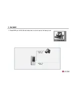
Page 21: ...5 DUMMY AWG24 2C DC 12V Please RS232 port of XID 500 with other device in order to operate the dummy mode Other Device AWG24 3C RS232 ...

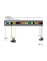
Page 22: ...ROOM 11 DUMMY RS232 WIEGAND Header Check the shunt connection of 2 3 and 5 6 GND 232 TXD 232 RXD 485 485 GND 232 RXD 232 TXD INPT1 GND INPT1 INPT2 GND INPT2 INPT3 GND INPT3 LOCK NO COM LOCK NC LOCK TR LOCK TR 전원 전원 LAN ...

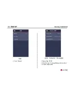
Page 23: ... 운용 운용 Customize Dummy설정 11 DUMMY Dummy Installation Set to Dummy Dummy Type RS232 Select the type of message Message Card number Confirm output mode ...

Page 24: ...6 LCM Connection ...

Page 25: ...24 2C DC 12V AWG24 2C DC 12V AWG24 3C RS 485 Door Lock TPS Room UTP Outdoor XID 500 Indoor XID 500 UTP AWG24 3C RS 485 RS485 port can connect with LCM LCM Power should be seperated with XID 500 XID3 0 LCM 파랑 초록 검정 Join RS485 wire ...

Page 26: ...Power Power TPS Room LCM RS485 port GND TRXD TRXD 485 485 GND 232 RXD 232 TXD INPT1 GND INPT1 INPT2 GND INPT2 INPT3 GND INPT3 LOCK NO COM LOCK NC LOCK TR LOCK TR 전원 전원 LAN 6 LCM Connections ...

Page 27: ...LCM 운용 Installation Set 운용모드 to 출입 Set to 단말기 해체 경보음 In Out Set on the direction purpose LCM Type XID3 0 DoorLock 설정 None Input 1 InsideOpen None Input 2 Door Status NO or NC Input 3 Lock Status None 6 LCM Connections ...

Page 28: ...7 Additional Relay ...

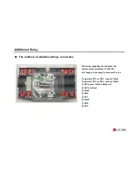
Page 29: ...minimum requirements of 12V 5A Left image is showing 2 poles and 8 pins To operate NC1 or NO1 connect Pole1 To operate NC2 or NO2 connect Pole2 12V power for the Relay coil 12V Coil Gnd Pole1 NO1 NC1 Pole2 NO2 NC2 The method of additional Relay connection ...

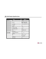
Page 30: ... MIFARE Physical Size mm 84 X 164 X 22 8 Weight g 260 Interface Communication Interface RJ45 TCP IP 10 100T RS 485 RS 232 USB for Printer USB for F W Upgrade Wiegand Output TTL Built in Relay 1 Expandable Function Additional Relay Control 1 12V External Relay Wireless LAN SAM 1 ...

Page 31: ...lay 4 3 color touch screed Humidity 90 Tamper Switch Operating Voltage 12 VDC Audio Output Power 1 0 W WDT HW MICOM SW RTC Battery Yes Environment Specification Operating Temperature 20 50 C Humidity 90 ESD Contact 8 kV Air 15 kV Certification KC SRRC CE Water Proof IP65 XID 500 Product Specifications ...

Page 32: ... Input VIH V 12 VIL V GND Low Pull up resistance Ω 10 K Wiegand Output VOH V 5 VOL V GND Low Pull up resistance Ω 4 7 K Relay Relay Type Dry Switching capacity A 2 Max Switching power resistive 60W Max Switching voltage VDC 220 XID 500 Product Specifications ...

Page 33: ...on If this equipment does cause harmful interference to radio or television reception which can be determined by turning the equipment off and on the user is encouraged to try correct the interference by one or more of the following measures 1 1 Reorient or relocate the receiving antenna 1 2 Increase the separation between the equipment and receiver 1 3 Connect the equipment into an outlet on a ci...

Reviews: