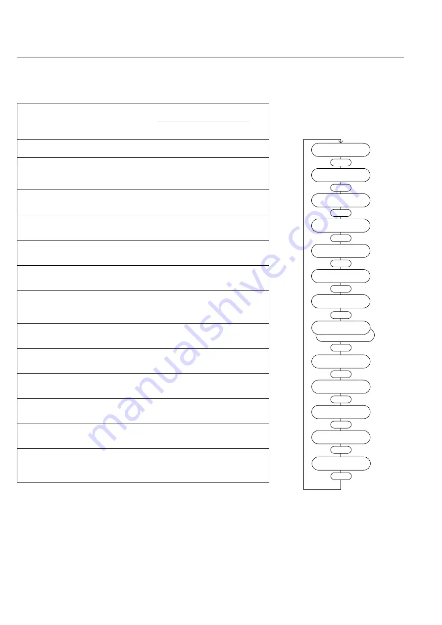
LEYBOLD MAG W 2010 C Operating Instructions Manual Download Page 32

4.3.1 Basic menu

Menu item

Description

Adjustable value / option

Ac-

cess

min.

max.

stan-

Unit

value

value

dard

Ready

Operating display

-

-

-

-

-

Freq. Setpoint

Sets the speed for operation

150

480

480

Hz

r/w

!! Every change is directly written
into the pump’s data storage
and is valid immediately!!

Operation Hours Total operating hours of the pump

actual value

h

r

Motor Temp.

Motor temperature

actual value

°

C

r

Converter Temp. Temperature of the power 

actual value

°

C

r

electronic

Bearing Temp.

Temperature of the magnetic 

actual value

°

C

r

bearing

Actual Value TMS Temperature of the Temperature

actual value

°

C

r

Management System

Cooling Temp.

Cooling water temperature

actual value

°

C

r

Actual  PVW 13

Rotor displacement in the 
magnetic bearing  

actual value

%

r

plane VW13

Actual PVW 24

Rotor displacement in the 
magnetic bearing  

actual value

%

r

plane VW24

Actual PZ 12

Rotor displacement in the 
magnetic bearing  

actual value

%

r

axis Z12

Power

Power consumption of the drive

actual value

W

r

Software Version

Actual software version

actual value

-

r

Plug-in control

32

GA 05.136/2.02 - 10/98

Ready

0.0 A       0 Hz

Enter

Freq. Setpoint

480 Hz

Enter

Operation Hours

0.00 h

Enter

Motor Temp.

50 

°

C

Enter

Converter Temp.

40 

°

C

Enter

Bearing Temp.

50 

°

C

Enter

Actual PVW 13

10%

Enter

Actual PVW 24

10%

Enter

Actual PZ 12

5%

Enter

Power

400 W

Enter

Actual Value TMS

Not Active

Enter

Not Active

Cooling Temp.

20 

°

C

Enter

r (read)  = value can only be read
r /w (read/write)   = value can be read and written

4.3 Operating menu

Software Version

104.xx

Enter

Summary of Contents for MAG W 2010 C

Page 1: ...lar Pump with Magnetic Bearing MAG DRIVE 2000 Electronic Frequency Converter Software version 1 4 xx Cat Nos 121 32 121 35 36 Operating Instructions Vacuum Solutions Application Support Service LEYBOL...

Page 2: ...f the menu 35 5 Maintenance 36 5 1 Removing the pump from the system 36 5 2 Service at Leybold s 37 6 Troubleshooting 38 6 1 Warning messages 39 6 2 Failure messages 40 6 3 Malfunctions 43 Certificati...

Page 3: ...he pump cannot handle gases or media e g AlCl3 which form deposits inside the pump Ignition danger During operation the pressure inside the MAG is so low that there is no danger of ignition at pressur...

Page 4: ...commutator is used to power the rotor Drive voltage for the motor and the operating voltage for the magnetic bearing are supplied by the MAG DRIVE frequency converter It also handles the automatic mo...

Page 5: ...05 136 2 02 10 98 Description 5 Fig 1 Front panel X14 Connection control plug X19 Mains connection X20 Connection magnetic bearing X21 Connection pump motor and TMS Fig 2 Rear panel with connections...

Page 6: ...to 0 65 mbar l s 1 30 to 40 sccm Connection VCR Nut 1 4 6 GA 05 136 2 02 10 98 1 5 Standard specification MAG The turbomolecular pumps are shipped complete sealed in a PE bag containing a desiccant Th...

Page 7: ...t is not protected against the ingress of water with damaging effects An increased degree of protection e g IP54 can only be implemented by mounting the converter in an additional housing 7 GA 05 136...

Page 8: ...Description 8 GA 05 136 2 02 10 98 Fig 3 Dimensional drawing of the MAG DRIVE dimensions in mm 122 4 198 3 3 with cable length 1 5 m with cable length 10 or 20 m...

Page 9: ...pressure Rotor speed 480 Hz Purge gas flow 36 sccm Nitrogen with splinter guard Forepump D 65 B WS 251 Pipe 1 m DN 40 according to PNEUROP 1500 1000 500 0 2000 10 2 10 1 1 Torr 10 3 10 4 l s MAG W 201...

Page 10: ...Description 10 GA 05 136 2 02 10 98 Fig 6 MAG W 2010 C Dimensions in mm...

Page 11: ...pump while connecting or remo ving the MAG The MAG is shipped in a sealed PE bag with desiccant Do not open the sealed package until immediately befo re installing Do not remove the covers and blankin...

Page 12: ...103 Gy 1 Gy Gray 100 rad The ambient temperature must not exceed 40 C 104 F The noise level when the pump is running is below 70 dB A No acoustic insulation is required 2 4 Connecting the MAG to the v...

Page 13: ...eration without the splinter guard are excluded from warranty Caution Install the splinter guard as shown in Fig 9 Installing the splinter guard upside down may lead to contact between splinter guard...

Page 14: ...G is permanently flanged to a vacuum chamber with a weight exceeding 500 kg it will not be necessary to secure it in any other way The vacuum chamber must be securely attached to the floor or a solid...

Page 15: ...98 18 l l 15 mm in aluminium l 10 mm in steel Sealing FPM Splinter guard Max torque 60 000 Nm Fig 11 Fixing the intake flange Bolts M10 x 35 M10 x 40 Quality 12 9 according to DIN 898 0 2 yield stren...

Page 16: ...for operating the MAG We recommend our RUVAC blower for this purpose or our DRYVAC 251 501 systems Fig 12 shows schematically the design of a pump system incorporating a MAG with an additional foreli...

Page 17: ...stallation 17 GA 05 136 2 02 10 98 M Mq M 150 Nm Mq 150 Nm Fig 13 Maximum torques for the forevacuum connection and connecting the cooling water Cooling water out 1 2 tube Cooling water in 2 x 3 8 tub...

Page 18: ...e 3 57 mmol l Further information on request Connect the cooling water to the connectors see Fig 13 In case you want to use only 1 inlet connector close the other one with the blind plug provided with...

Page 19: ...You may use a flow controller to ensure the flow Inadequate purge gas flow voids the warranty Connect purge gas to the VCR nut 1 4 as shown in Fig 15 Warning Monitor the purge gas continuously Insuffi...

Page 20: ...alling the MAG DRIVE The converter can be installed in a 19 cabinet It is 1 2 of 19 wide and has 3 height units For easier installation we offer an installation frame see Section 1 7 If you use this i...

Page 21: ...connection has no function and will be covered with a supplied cap Also refer to Fig 16 2 8 3 Control plug X14 Emergency off Make sure that pins 47 and 48 are connected via a jum per if you don t con...

Page 22: ...d to output motor current actual frequency motor temperature rotor displacement signals PW24 PV13 PZ12 The output value can be increased or reduced by a scale factor see Section 4 3 2 Settings Convert...

Page 23: ...mp standstill Start command Power supply o k X14 1 X14 34 X14 20 X14 3 X14 36 X14 19 X14 2 Threshold Threshold Actual frequency No failure Relay Failure Relay Normal Operation Normal operation Motor o...

Page 24: ...or 29 is connected at the digital input Remote Start if Remote is active The functions Start and Remote are active if a Low sig nal GND e g Pins 27 or 43 is connected at the digital input 1 5 6 9 1 5...

Page 25: ...tor to make contact with the touch down bearings This will cause increased wear Do not disconnect the MAG and MAG DRIVE while they are operating If MAG and MAG DRIVE have been disconnected accidently...

Page 26: ...ormation in the pump The backing pump may be switched off once the MAG has stopped If the MAG has been used for pumping corrosive gases it should be purged with dry nitrogen for one hour before switch...

Page 27: ...connector X14 X14 11 not connected Start Stop via the operator control panel Jumper X14 11 X14 10 Start Stop via control input X14 12 0 1 P12 0 1 2 S R Q Q 1 s 0 1 2 1 1 START REMOTE 15 V X14 11 X14 1...

Page 28: ...ayed The backing pump and the MAG can be switched on simultaneously In such a situation the MAG serves from the very outset as an effective baffle Switching off Press the STOP key Deceleration 20 0 A...

Page 29: ...ing display Stop Stops the pump Returns to the operating display from the programming menu Acknowledges a failure after the cause of the failure has been removed Increases a parameter value or proceed...

Page 30: ...celerate up to the frequen cy setpoint Overload The speed is continuously monitored and controlled If the speed even at maximum current cannot be held at the setpoint as a result of external influence...

Page 31: ...time START command Mains ok Frequency P 25 x P24 Mains failure Mains failure Frequency P25 x P24 Frequency P25 x P24 Mains failure STOP command If a failure occurs the pump is decelerated Frequency 1...

Page 32: ...re actual value C r Actual PVW 13 Rotor displacement in the magnetic bearing actual value r plane VW13 Actual PVW 24 Rotor displacement in the magnetic bearing actual value r plane VW24 Actual PZ 12 R...

Page 33: ...earing temp 100 C 10Vxscale factor V Actual PVW13 100 10Vxscale factor V Actual PVW24 100 10Vxscale factor V Actual PZ12 100 10Vxscale factor V Scale Factor Scale factor for the analog output 0 2 1 r...

Page 34: ...al operation corresponding to the 35 99 95 r w frequency setpoint Max Accel Time Monitor time for acceleration and overload 600 3600 1000 s r w Pump Type Displays the installed pump type Installed pum...

Page 35: ...urge Gas No Cooling Water Frequency Set Converter Enter Motor Current Option Relay 1 Bearing Temp Scale factor 1 0 x Enter Freq Setpoint Analog Input 2 No Function Enter Start Delay 0 s Enter Display...

Page 36: ...e the pump for two hours with the backing pump running This helps to remove a large quantity of the pro cess gases from the pump We recommend purging the pump via the intake flange and the purge valve...

Page 37: ...d To do so you must use a pre printed form which we shall send to you upon request A copy of this form is printed at the end of the Operating Instructions Declaration of Contamination of Vacuum Equipm...

Page 38: ...can be cancelled once the pump has come to a stop and after the malfunction has been rectified do so with the STOP function button or serial interface Warning The MAG shall be stopped completely and t...

Page 39: ...lso Section 2 6 Allow pump to cool down between the cycles Allow converter to cool down between the cycles Refer to Section 2 8 for the correct mounting of the converter in a rack max ambient tem pera...

Page 40: ...its See also Section 2 6 Allow pump to cool down between the cycles Step 1 Check pump temperature sensor Check pump connector X23 In particular measure resistance between pins X23 v and X23 u as well...

Page 41: ...contact Leybold service Check the chamber pressure during the operation Refer to Section 3 1 for correct venting of the pump Contact Leybold service Check BEARING connector and cable for damages or be...

Page 42: ...k Repeat step 2 of failure Motor Temp Contact Leybold service if the resistance of the sensor is less than 1 62 k Contact Leybold service Check if the BEARING cable is connected to the pump and the c...

Page 43: ...n again If the converter still malfunctions contact Leybold service Check and replace valve if required Leave the pump system run for 3 to 5 hours to reach a pressure below 10 5 mbar Operate the conve...

Page 44: ...3 EWG When using the appropriate Leybold accessories e g connector lines and when powering the pump with the specified Leybold frequency converters the protection level prescribed in the EMC Guideline...

Page 45: ...t indicated solely for fitting in another machine Commissioning is prohibited until the conformity of the end product with EC directive 89 392 EEC has been established Standards applied EN 60204 1 EN...

Page 46: ...th and safety regulations specified in the EEC Directives This declaration is no longer valid if the product is modified without us being in full agreement The product conforms to the EEC Low Voltage...

Page 47: ...were made taking into account the following standards EN 50081 Part 2 EN 50082 Part 2 Note Attention must be paid to the information provided on proper installation with respect to elektromagnetic com...

Page 48: ...pment and components which have been contaminated by biological explosive or radioactive substances will not accepted without written evidence of decontamination Please list all substances gases and b...

Page 49: ...umber Complaint Process OEM Equipment Name and Model Process Gas Was the turbopump replaced Yes No If yes replacement pump P N replacement pump S N Date Installed Date Removed Date Received Date Exami...

Page 50: ...AG W 2000 C CT MAG W 1600 C CT MAG 2000 C CT MAG W 2000 C CT GA 05 130 1 02 December 1997 Valid for Converters MAG DRIVE L MAG DRIVE L2 Trouble shooting incomplete MAG DRIVE L MAG DRIVE L2 Trouble sho...

Reviews: