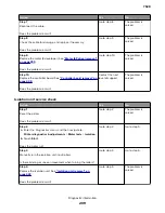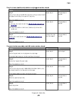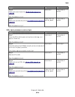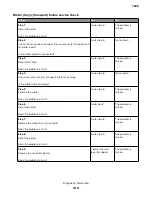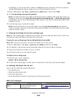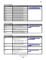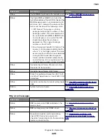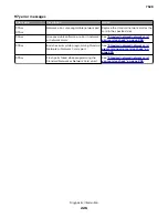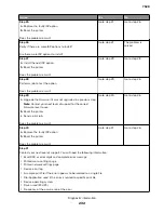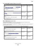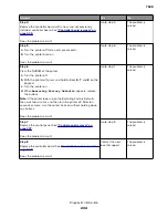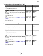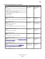
Action
Yes
No
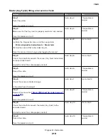
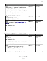
Step 6
Replace the controller board. See
board assembly removal” on page 451
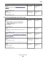
Does the problem remain?
Contact the next
level of support.
The problem is
solved.
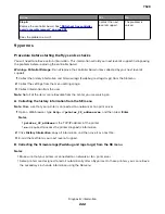
9yy errors
Procedure before starting the 9yy service checks
You will need to retrieve certain information. This information will aid your next level of support in diagnosing
the problem before replacing the controller board.
Warning—Potential Damage:
Do not replace the controller board unless directed by your next level of
support.
1
Collect the history information and firmware logs (Fwdebug and logs.tar.gz) from the SE menu.
2
Collect the settings from the menu settings page.
3
Collect information from the user.
Note:
Not all of the items are retrievable from the printer you are working on.
A. Collecting the history information from the SE menu
Note:
Make sure that your printer is connected to a network or to a print server.
1
Open a Web browser, type
http://printer_IP_address/se
, and then press
Enter
.
Notes:
•
printer_IP_address
is the TCP/IP address of the printer
•
se
is required to access the printer diagnostic information
2
Click
History Information
, copy all information, and then save it as a text file.
3
E-mail the text file to your next level of support.
B. Collecting the firmware logs (Fwdebug and logs.tar.gz) from the SE menu
Notes:
•
Make sure that your printer is connected to a network or to a print server.
•
Some printers are designed to restart automatically after a 9yy error. On these printers, you can retrieve
the secondary crash code information using the SE menu.
7528
Diagnostic information
222
Summary of Contents for XC4150
Page 34: ...7528 34 ...
Page 276: ...7528 276 ...
Page 294: ...Scan SE Scanner Info 7528 Service menus 294 ...
Page 317: ...3 Remove the screw B from the lower left side of the cover B 7528 Repair information 317 ...
Page 320: ...3 Remove the three screws A 7528 Repair information 320 ...
Page 327: ...3 Remove the E clip B 4 Remove the E clip C 7528 Repair information 327 ...
Page 358: ...5 Remove the two screws D from under the gear box 7528 Repair information 358 ...
Page 360: ...3 Disconnect the cable A from the LVPS 7528 Repair information 360 ...
Page 370: ...3 Disconnect the motor cable A A 7528 Repair information 370 ...
Page 371: ...4 Remove the four screws B and then remove the motor B 7528 Repair information 371 ...
Page 374: ...4 Disconnect the cable B 5 Remove the screw C securing the HVPS C 7528 Repair information 374 ...
Page 400: ...14 Remove the clip M and then remove the spacer 7528 Repair information 400 ...
Page 403: ...7528 Repair information 403 ...
Page 414: ...5 Remove the screw C from the printhead 7528 Repair information 414 ...
Page 429: ...8 Route the ADF cable through the flatbed 9 Remove the ADF 7528 Repair information 429 ...
Page 437: ...7 Disconnect the two cables B on the controller board 7528 Repair information 437 ...
Page 443: ...5 Remove the screw D and then remove the scanner tilt D 7528 Repair information 443 ...
Page 478: ...7528 478 ...
Page 485: ...7528 485 ...
Page 487: ...Assembly 1 Covers 1 2 4 6 7 8 9 1 14 10 3 5 13 13 11 11 12 7528 Parts catalog 487 ...
Page 489: ...Assembly 2 Covers 2 14 7528 Parts catalog 489 ...
Page 491: ...Assembly 3 Control panel 5 4 3 2 1 7528 Parts catalog 491 ...
Page 493: ...Assembly 4 ADF and flatbed 1 3 11 10 4 9 5 6 7 8 2 7528 Parts catalog 493 ...
Page 495: ...Assembly 5 Fuser 1 7528 Parts catalog 495 ...
Page 497: ...Assembly 6 Transfer module 1 2 7528 Parts catalog 497 ...
Page 499: ...Assembly 7 Paper feed 8 2 1 2 4 7 3 5 5 6 7528 Parts catalog 499 ...
Page 501: ...Assembly 8 Paper path 1 8 6 2 3 1 10 5 7 9 4 7528 Parts catalog 501 ...
Page 503: ...Assembly 9 Paper path 2 1 4 2 5 10 3 6 9 7 8 7528 Parts catalog 503 ...
Page 505: ...Assembly 10 Duplex 9 8 3 3 7 6 1 1 2 4 5 7528 Parts catalog 505 ...
Page 507: ...Assembly 11 Electrical 16 2 3 4 5 7 8 9 11 12 13 15 6 1 14 10 7528 Parts catalog 507 ...
Page 510: ...7528 Parts catalog 510 ...
Page 511: ...Assembly 12 550 sheet tray option 1 2 1 7528 Parts catalog 511 ...
Page 513: ...Assembly 13 550 sheet tray option 2 1 2 3 4 12 11 6 13 5 9 10 7 8 7528 Parts catalog 513 ...
Page 515: ...Assembly 14 Adjustable stand 2 2 3 3 1 7528 Parts catalog 515 ...
Page 518: ...7528 Parts catalog 518 ...
Page 520: ...7528 520 ...
Page 527: ...3 Apply the changes 7528 Appendix B Options and features 527 ...
Page 528: ...7528 528 ...
Page 554: ...7528 554 ...
Page 568: ...7528 Part number index 568 ...
Page 574: ...7528 Part name index 574 ...


