background image

Repair information

4-47


4513-200, -220, -230

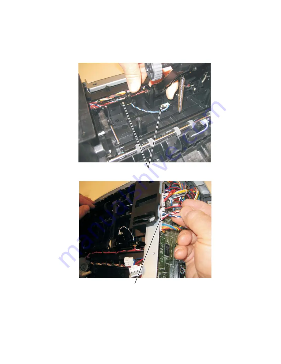
Paper input and duplex sensor assembly removal

1.

Remove the right side cover. See 

“Right side cover assembly removal” on page 4-53

.

2.

Remove the duplex. See 

“Duplex removal” on page 4-11

.

3.

Remove the two screws (A) from the sensors.

4.

Disconnect the sensor cable (B) from the controller board.

5.

Remove the paper input and duplex sensor assembly.

A

B

Summary of Contents for E260 Series

Page 1: ...e of contents Start diagnostics Safety and notices Trademarks Index Lexmark and Lexmark with diamond design are trademarks of Lexmark International Inc registered in the United States and or other countries Lexmark E260 E260d E260dn Revision date July 1 2013 ...

Page 2: ...g any obligation to you References in this publication to products programs or services do not imply that the manufacturer intends to make these available in all countries in which it operates Any reference to a product program or service is not intended to state or imply that only that product program or service may be used Any functionally equivalent product program or service that does not infr...

Page 3: ...ST sequence 2 2 Light patterns and error messages 2 3 Common primary light patterns 2 4 Primary codes 2 7 Common secondary light patterns 2 16 Secondary error codes 2 18 Service codes 2 28 Messages and error codes 2 36 User attendance messages 2 36 Paper jam error codes 200 series 2 36 Service error codes 2 42 Diagram of the printer menus 2 49 Symptom tables 2 50 POST symptom table 2 50 Printer sy...

Page 4: ...rface removal 4 13 Fan removal 4 16 Front access door removal 4 17 Fuser removal 4 20 Left print cartridge guide 4 23 Left side cover removal 4 24 Lower front cover removal 4 26 LVPS HVPS removal 4 27 Main motor gear drive removal 4 30 Manual feed clutch removal 4 32 Manual feed solenoid removal 4 34 Media ACM ASM feeder removal 4 35 Media feed clutch removal 4 38 Media manual input sensor removal...

Page 5: ...3 200 220 230 Controller board connector pin values 5 2 Preventive maintenance 6 1 Safety inspection guide 6 1 Lubrication specifications 6 1 Parts catalog 7 1 How to use this parts catalog 7 1 Index I 1 Part number index I 3 ...

Page 6: ...vi Lexmark E260 E260d E260dn 4513 200 220 230 ...

Page 7: ...oder bei ordnungsgemäßer Wartung durch den Kundendienst Laserbestrahlung die Klasse I übersteigen würde Menschen keinesfalls erreicht Avis relatif à l utilisation de laser Pour les Etats Unis cette imprimante est certifiée conforme aux provisions DHHS 21 CFR alinéa J concernant les produits laser de Classe I 1 Pour les autres pays cette imprimante répond aux normes IEC 60825 1 relatives aux produi...

Page 8: ...seneto de potássio de 7 milliwatts operando numa faixa de comprimento de onda entre 655 e 675 nanómetros O sistema e a impressora laser foram concebidos de forma a nunca existir qualquer possiblidade de acesso humano a radiação laser superior a um nível de Classe I durante a operação normal a manutenção feita pelo utilizador ou condições de assistência prescritas Laserinformatie De printer voldoet...

Page 9: ...ohitettaessa olet alttiina näkymättömälle lasersäteilylle Älä katso säteeseen VARNING Osynlig laserstrålning när denna del är öppnad och spärren är urkopplad Betrakta ej strålen Laser notis Denna skrivare är i USA certifierad att motsvara kraven i DHHS 21 CFR underparagraf J för laserprodukter av Klass I 1 I andra länder uppfyller skrivaren kraven för laserprodukter av Klass I enligt kraven i IEC ...

Page 10: ...ts d IEC 60825 1 Els productes làser de classe I no es consideren perillosos Aquesta impressora conté un làser de classe IIIb 3b d arseniür de gal li nominalment de 7 mil liwats i funciona a la regió de longitud d ona de 655 675 nanòmetres El sistema làser i la impressora han sigut concebuts de manera que mai hi hagi exposició a la radiació làser per sobre d un nivell de classe I durant una operac...

Page 11: ...Notices and safety information xi 4513 200 220 230 ...

Page 12: ...xii Lexmark E260 E260d E260dn 4513 200 220 230 ...

Page 13: ...bole indique la présence d une tension dangereuse dans la partie du produit sur laquelle vous travaillez Débranchez le produit avant de commencer ou faites preuve de vigilance si l exécution de la tâche exige que le produit reste sous tension Norme di sicurezza La sicurezza del prodotto si basa sui test e sull approvazione del progetto originale e dei componenti specifici Il produttore non è respo...

Page 14: ... precauciones necesarias PRECAUCIÓN este símbolo indica que el voltaje de la parte del equipo con la que está trabajando es peligroso Antes de empezar desenchufe el equipo o tenga cuidado si para trabajar con él debe conectarlo Informações de Segurança A segurança deste produto baseia se em testes e aprovações do modelo original e de componentes específicos O fabricante não é responsável pela segu...

Page 15: ...st producte està orientada exclusivament a professionals i no està destinada a ningú que no ho sigui El risc de xoc elèctric i de danys personals pot augmentar durant el procés de desmuntatge i de servei d aquest producte El personal professional ha d estar ne assabentat i prendre les mesures convenients PRECAUCIÓ aquest símbol indica que el voltatge de la part de l equip amb la qual esteu treball...

Page 16: ...mendations to prevent problems 7 Parts catalog contains illustrations and part numbers for individual FRUs Change history Conventions Note A note provides additional information Warning A warning identifies something that might damage the product hardware or software There are several types of caution statements Revision date Updates 2013 07 01 Updated Media ACM ASM feeder removal on page 4 35 201...

Page 17: ...Conventions xvii 4513 200 220 230 CAUTION This type of caution indicates a hot surface CAUTION This type of caution indicates a tipping hazard ...

Page 18: ...xviii Lexmark E260 E260d E260dn 4513 200 220 230 ...

Page 19: ...ual For information on E460dn and E460dw see the 4513 630 63W 6EW service manual Maintenance approach The diagnostic information in this manual leads to the correct field replaceable unit FRU or part Use the error code charts symptom index and service checks to determine the symptom and repair the failure See Diagnostics information on page 2 1 for more information See Repair information on page 4...

Page 20: ...260d E260dn 4513 200 220 230 Overview of the operator panel The operator panel consists of these items LED operator panel Two buttons Cancel and Continue Six lights Error Paper Jam Load Paper Toner Low Ready and Continue ...

Page 21: ...lash memory 64MB x x 256MB x x Optional font cards DBCS Option slots Memory slots 1 1 Flash memory option card x x Item 4513 200 220 Lexmark E260 E260d 4513 230 Lexmark E260dn Print resolution 1200 Image quality 2400 Image quality 600 X 600 dpi 1200 X 1200 dpi 1200 Image quality is defined as 600 dpi with 2 bit IET Image Technology default mode for all models 2400 Image quality is defined as 600 d...

Page 22: ...image x x Compatibility Windows Macintosh Linux Windows Macintosh Linux Standard local connections Parallel USB Standard network connections Ethernet 10 100 Base Tx x Wireless ethernet 802 11b g n x x Optional local connections Optional network connections external print server support All models are USB 2 0 Certified devices supporting Hi Speed data transfer Includes the HD photo image format Inc...

Page 23: ...ed print duplex Integrated Integrated Envelope conditioning x x Available output trays Standard 150 sheet sensing bin Toner and photoconductor Toner cartridge 1 000 standard pages SWE 3 500 standard pages 1 000 standard pages SWE 3 500 standard pages High toner cartridge x x Photoconductor kit Up to 30 000 Up to 30 000 Declared value in accordance with ISO IEC 19752 Up to 30 000 pages based on an ...

Page 24: ...ment Universal Plain paper transparency bond letterhead preprinted colored paper light paper heavy paper rough cotton custom type x 60 163 g m 16 43 lb 1 all medias Card stock 120 163 g m 16 43 lb Index Bristol 75 163 g m 46 100 lb Tag 1 7 9 10 DL C5 B5 other Envelopes Rough envelopes 75 g m 20 lb 1 Duplex A4 letter legal oficio Mexico folio Plain paper recycled bond letterhead preprinted colored ...

Page 25: ... 0 mm C Upper end feed rolls C D 59 8 mm D Input sensor D E 44 9 mm E Transfer roll E F 112 7 mm F Fuser F G 21 4 mm G Fuser exit rolls G H 114 8 mm H Fuser exit sensor H I 7 5 mm I Exit rolls I J 17 0 mm J Exit sensor I K 211 7 mm K Duplex unit K L 93 4 mm L Duplex sensor L M 8 4 mm M Auto compensator G H K L D M A B C E F J I ...

Page 26: ...ll indicators on the 250 sheet tray before pushing the tray into the printer Make sure paper guides are positioned before loading the paper or specialty media Do not remove trays while a job is printing Before loading transparencies fan the stack to prevent sheets from sticking together Do not use envelopes that Have excessive curl Are stuck together Are damaged in any way Contain windows holes pe...

Page 27: ...ield Replaceable Unit HBP Host Based Printing HVPS High Voltage Power Supply LCD Liquid Crystal Diode LED Light Emitting Diode LSU Laser Scanning Unit LVPS Low Voltage Power Supply NVRAM Nonvolatile Random Access Memory PC Photoconductor PCL Printer Control Language POR Power On Reset POST Power On Self Test PPDS Personal Printer Data Stream PRC People s Republic of China TAR Toner Add Roll SDR Sy...

Page 28: ...1 10 Lexmark E260 E260d E260dn 4513 200 220 230 ...

Page 29: ...c tools to aid in providing corrective action for a malfunctioning printer To determine the corrective action to repair a printer look for the following information A description of a problem see Diagram of the printer menus on page 2 49 Information from the operator panel of the printer Models E260 E260d and E260dn have an operator panel containing lights and buttons Warning Paper clips are commo...

Page 30: ... sequentially 3 After the lights quit flashing the light flashes until the fuser comes up to temperature 5 20 additional seconds depending on the initial temperature of the fuser and then stays on 4 If there is a problem in the printer such as a paper jam then the panel lights indicate the problem See Common primary light patterns on page 2 4 for more information 5 The printer cycles down into sta...

Page 31: ... secondary patterns In which case when double clicking the pattern does not change All service errors are indicated by all lights flashing as the primary notification or code The secondary code indicates an area or function which has the error Additional tertiary codes used for service see Service tertiary error codes on page 2 30 indicate specific errors See Service codes on page 2 28 Note If dat...

Page 32: ...e Print Quality Test Page Programming Flash 8 Hex Trace Ready 8 x Waiting 8 Flushing buffer Resolution reduced 9 Not ready printer is offline 9 Close door or Insert Cartridge Unsupported Flash Option Installed 10 Cancel job Reset printer Restore factory defaults 10 Invalid engine code Invalid network code 11 Resolution reduced while canceling job 11 Toner cartridge region mismatch Change cartridge...

Page 33: ...l follow this code Printer Condition Page Toner low 11 Ready and Toner Low Power Saver and Toner Low Demo Mode Ready and Toner Low Hex Trace Ready and Toner Low x Busy and Toner Lower Defragmenting Flash and Toner Low Formatting Flash and Toner Low Printing Directory and Toner Low Printing Font List and Toner Low Printing Menu Settings and Toner Low Printing Print Quality Test pages and Toner Low ...

Page 34: ...conductor Defragmenting Flash and Replace Photoconductor Formatting Flash and Replace Photoconductor Printing Directory and Replace Photoconductor Printing Font List and Replace Photoconductor Printing Menu Settings and Replace Photoconductor Printing Print Quality Test pages and Replace Photoconductor Programming Flash and Replace Photoconductor Resolution reduced Flushing buffer and Replace Phot...

Page 35: ...n Power Saver mode Action Send a print job Press Continue to print the menu settings pages for a list of current printer settings Press and hold Cancel to reset the printer Meaning The printer is in the Ready state and the Demo Mode is active The printer is ready to receive and process data from a host system Action Press Continue briefly to print the next Demo page ...

Page 36: ... pages to print The Ready light flashes as the pages print The Ready light is on when the printing stops Press and release Cancel to cancel printing Press and hold Cancel to reset the printer x Meaning The printer is in the Ready mode and Hex Trace is active Action Advanced users can use Hex Trace to help troubleshoot printing problems After resolving the problem turn off the printer to exit Hex T...

Page 37: ...t job is reduced from 600 dots per inch dpi to 300 dpi to prevent a memory full error Action Wait until the control panel returns to Ready to print other jobs Press and release Cancel to cancel the print job Press and hold Cancel to reset the printer Meaning The printer is not ready to receive or process data or the printer ports are offline Action Press and release Continue to return to the Ready...

Page 38: ... supported flash option The printer will automatically reset Meaning The printer memory is too full to collate the print job Action Press and release Continue to clear the message and continue printing the job The job may not print correctly Press and release Cancel to cancel the print job Press Cancel to reset the printer Meaning The current print job is canceled The printer is resetting to the u...

Page 39: ...and the resolution of the page belonging to the currently printing job has been reduced from 600 dpi to 300 dpi in order to prevent a Memory Full error Action Pressing Cancel will cancel the print job Other buttons are ignored Meaning The printer is ready to receive and process data In addition the toner in the toner cartridge is getting low Action Press and release Continue to clear the light seq...

Page 40: ...ll a new toner cartridge that matches the region of the printer Meaning The photoconductor is almost full and should be replaced soon Note The Toner Alarm must be turned on in the driver for this message to appear The factory default is Off Action Press and release Continue to clear the light sequence and continue printing Replace the photoconductor kit Meaning The photoconductor kit is full and m...

Page 41: ... printing has stopped Action Press Continue twice to see the secondary code See Service codes on page 2 28 to locate the problem Meaning The printer has one of the following errors Memory is full insufficient to save what is in the buffer A page is too complex to print or is shorter than the set page margins Resolution of a formatted page is reduced to 300 dpi A font error occurred Communication w...

Page 42: ...e secondary error code Press Continue to resume printing once all the jammed pages are cleared from the paper path Meaning The output bin is full Action Remove printed pages from the output bin Press Continue to clear the error code Meaning The printer is out of print media at the indicated source Action Load print media into the indicated tray and press Continue to resume printing Press Cancel to...

Page 43: ... print media in the multi purpose feeder or manual feeder Action Load print media into the manual feeder Press Continue to resume printing Press Cancel to reset the printer Meaning The printer prompts to load side 2 of a single sheet of print media in Tray 1 for duplex printing Action Load side 2 of a single sheet of print media in Tray 1 Press Continue to resume printing Press Cancel to reset the...

Page 44: ...or paper jams When the Paper jam and Continue lights are both on a paper jam has occurred with a secondary error code Printer Condition Page 200 Paper jam at the input sensor 18 201 Paper jam between the input and exit sensor 18 202 Paper jams at the exit sensor 18 231 Paper jam duplex rear 18 232 Paper jam duplex front 19 233 Paper jam duplex 19 234 Paper jam duplex location unknown 19 241 Paper ...

Page 45: ...sufficient collation area 21 Defective flash 21 Network interface errors 21 Resource save off deficient memory 22 PPDS font error 22 Invalid configuration 23 Insufficient defrag memory 22 ENA connection lost 23 Host interface disabled 23 Memory full 23 Short media 24 Flash full 24 Invalid engine code 24 Invalid network code 25 Toner cartridge region mismatch 25 Change toner cartridge invalid refil...

Page 46: ... or in the manual feeder Action Open the front door remove the print cartridge and clear the paper jam Meaning A paper jam has occurred The jammed media is most likely in the fuser area under the toner cartridge assembly Action Open the front door remove the print cartridge and clear the paper jam Meaning A paper jam has occurred as the print media is exiting the printer Action Open the rear door ...

Page 47: ...he duplex door and clear the paper jam Meaning A paper jam has occurred somewhere around the duplex unit before making the manual input sensor Action Remove the tray open the duplex door and clear the paper jam Paper may also be accessible inside the rear door Meaning A paper jam has occurred in Tray 1 Action Clear the paper jam after removing Tray or and or Tray 2 Meaning A paper jam has occurred...

Page 48: ...n the page is too complex that is too large for the printer memory Action Press Continue to clear the error code and continue processing the print job some of the print data may be lost To avoid this error in the future Reduce the complexity of the page by reducing the amount of text or graphics on the page and deleting unnecessary download fonts or macros Set Page Protect to On in the Local Print...

Page 49: ...Press and release Cancel to cancel the print job Press and hold Cancel to reset the printer To avoid this error in the future Simplify the print job Reduce the complexity of the page by reducing the amount of text or graphics on the page and deleting unnecessary downloaded fonts or macros Install additional printer memory Meaning The printer detects a defective flash Action Press Continue briefly ...

Page 50: ...job Press Cancel to cancel the print job Meaning The printer memory does not have the free space necessary to collate the print job This may happen due to one of these errors Memory is full A page is too complex to print A page is shorter than the set page margins Memory is insufficient to save what is in the buffer Action Press Continue to clear the message and continue printing the job The job m...

Page 51: ...l port by selecting a value other than Disabled for the USB Buffer or Parallel Buffer item in the Local Printer Settings Utility Meaning The printer is processing data but there is not enough memory available to continue the job Action Press Continue to clear the message and continue printing the job the job may not print correctly Press and release Cancel to cancel the print job Press and hold Ca...

Page 52: ...code and continue printing the job Press Cancel to cancel the print job Meaning The printer signals that there is not enough free space in the flash memory mode to hold the resources that have been requested to be written to flash Action Press Cancel to cancel the print job Press Continue to clear the message and continue processing the job All downloaded fonts and macros that are not written to f...

Page 53: ... the installed toner cartridge Action Remove the toner cartridge and install a new toner cartridge that matches the region of the printer The settings cannot be changed without calling Lexmark for a one time change Meaning The toner in the toner cartridge is getting low or an invalid refill toner has been installed Action Press and release Continue to clear the light sequence and continue processi...

Page 54: ...er cartridge and shake it to extend the life or replace the toner cartridge if it is defective Replace the toner cartridge Turn the printer on Meaning The toner cartridge is not supported by the printer Action Press and release Continue to clear the light sequence and continue processing the print job Turn the printer off Remove the toner cartridge and replace it with a supported toner cartridge T...

Page 55: ...nformatted flash at power on Action Press Continue briefly to clear the message The flash is marked as bad and normal operation will continue Flash operations will not be allowed until flash is formatted Meaning The printer has detected that it requires the installation of a MICR cartridge in order to complete a print job that it has received Action Install a MICR cartridge and then close the cove...

Page 56: ...condary light pattern indicates a fuser toner sensor or fan error Double click for more information The tertiary light pattern indicates the fan has stalled Double click again and the original primary light pattern will appear Note The printer cannot directly determine that a fan has failed but can sense the higher temperature at the fuser or printhead If data is sent to the printer and all lights...

Page 57: ...Software 90x Software 91x DC motor or transfer roll 92x Fuser or toner sensor 93x Printhead drive motor 94x LVPS service error 95x Controller board NCRAM ROM or NAND 96 RAM memory 97x Network 98x Service paper port communication error 99x Service device error Programming error 40 and 41 Unsupported firmware card ...

Page 58: ...ere is a danger from hazardous voltage in the area of the product that is being worked on Unplug the product before beginning or use caution if the product must receive power in order to perform the task Controller software Codes 90x indicate a controller software error illegal trap For the other errors which indicate a faulty programming process or faulty component on the controller board replace...

Page 59: ... toner sensor or toner cartridge Multiple errors indicate replacing the corresponding part Service tertiary error codes fuser fan or toner sensor Lights Service secondary codes 91x Service tertiary codes 910 Service DC motor error 914 Tray 2 motor failure 917 Transfer roll circuity Lights Service secondary codes 92x Service tertiary codes fuser fan or toner sensor 920 Fuser below temperature when ...

Page 60: ...ion or engine card error Error code 940 indicates a communication failure between the RIP and engine processors Error codes 948 949 indicate engine card failure Lights Service secondary codes 93x Service tertiary codes printhead transport motor or RIP engine communicator 930 Printhead error wrong printhead is installed 931 Printhead error 932 Printhead error 933 Printhead error 934 Printhead error...

Page 61: ...rror Indicates an error in the RAM memory Lights Service secondary codes 95x Service tertiary codes NVRAM failure 950 Secure EEPROM data does not match NVRAM 951 Secure EEPROM failure 952 NVRAM CRC failure 954 NVRAM chip failure 955 Code ROM or NAND failed CRC 956 Processor failure 957 ASIC failure 958 NAND failure 959 SRAM failure Lights Service secondary codes 96x Service tertiary codes RAM memo...

Page 62: ...rror 972 Service network error 973 Service network error 974 Service network error 975 Unrecognizable network port 976 Unrecoverable software error in network port 977 Service network error 978 Bad checksum while programming port 979 Flash parts failed while programming port Lights Service secondary codes 98x Service tertiary codes paper port communication error 980 Service paper port communicatio...

Page 63: ...ontroller board error Indicates a failure with the device s equipment or controller board Lights Service secondary codes 99x Service tertiary codes device equipment check or device controller board error 990 Service device equipment check 991 Service device controller board failure ...

Page 64: ...ong over the input sensor Possible causes include multi sheet feed tray size sensing problem and media slippage First remove the PC kit and paper or debric at the input sensor Then inspect the flag on the input sensor It should rotate freely Replace the sensor if necessary Finally check the paper size settings in the printer and the driver 200 02 The main input sensor never became uncovered from t...

Page 65: ...nput sensor If the flag is loose then replace it See Media manual input sensor removal on page 4 42 Verify that the media is approved Inspect the wear strips in the input tray and replace if necessary 200 16 Transport motor error detected Inspect the main motor See Main motor service check on page 2 55 200 17 Took too long to ramp up transport motor 200 18 Manual feeder sensor never became uncover...

Page 66: ...that the narrow media flag rotates freely and securely If it is dislodged or broken then repalce the rear exit guide See Rear exit guide assembly with sensor and reversing solenoid removal on page 4 51 200 32 Media more than 14 inches too long over the manual feeder sensor Possible causes include multi sheet feed or pre staged media in the tray Verify that the media is approved Inspect the wear st...

Page 67: ...20 201 26 Page at fuser nip before fuser started ramping toward desired temperature Indicates code may be receiving more interrupts than intended 201 27 Page at fuser nip before fuser reached acceptable operating temperature Page arrived at fuser earlier than expected so it was probably staged prematurely 202 00 Paper jam around exit sensor Open the rear cover and look for obstructions in the path...

Page 68: ... jam while picking from the device 233 01 Page in duplex never picked 233 02 Feed error picking from the duplex 233 03 Paper never reached the input sensor but was detected at the manual feed sensor 234 01 Duplex sensor covered during warm up 235 01 Invalid duplex media Check the media Duplex supports A4 letter legal oficio and folio media sizes 241 00 Paper jam near tray 1 Remove the tray and ins...

Page 69: ... the paper path Check the pick tires for wear or paper dust Replace if necessary Check the wear strips and replace if necessary 251 00 Paper jam near the manual feeder Inspect the pick roller on the MPF or the rollers on the manual feed If the MPF pick roller is damaged or worn then replace the MPF For a printer with a manual feed only no MPF clean the roller 251 10 Second pick attempt failed from...

Page 70: ...check on page 2 54 920 01 Fuser took too long to heat up after transitioning to new enhanced mode 920 02 Fuser fell too far below desired temperature while printing 920 03 Fuser too cool while checking for slope change 920 04 Fuser too cool when heating to desired temperature after slope change 920 05 Fuser under temperature while printing 920 06 Fuser under temperature while printing 920 07 Fuser...

Page 71: ...printing 920 07 Fuser under temperature while printing 920 08 Fuser temperature did not increase after IR recovery 920 20 Belt fuser under temperature during steady state control This can occur in printing or standby modes 921 00 Under temperature during standby control 921 01 Fuser temperature did not reach standby temperature after two attempts 922 00 Fuser failed to ramp to target temperature 9...

Page 72: ...e This applies to the fuser and belt fusers 924 02 Open thermistor check failure The ADC failed to converge Possible noisy thermistor signal This applies to the fuser and belt fusers 925 xx Wrong fuser installed The fuser type stored in the cartridge ID does not match the actual fuser installed in the printer Fan service errors 927 00 Service fan error Replace the fan See Cooling fan service check...

Page 73: ...osed loop error amp Ki failed to converge 935 20 Printhead closed loop error enable offset controller state 935 21 Printhead closed loop error load scan regs state 935 22 Printhead closed loop error fwd and rev capture times differ by too much 935 23 Printhead closed loop error check sweep accuracy state 935 25 Printhead closed loop error off resonant PI effort state 935 26 Timed out on POR sweep ...

Page 74: ...r operator panel See Controller board service check on page 2 52 or Operator panel service check on page 2 57 951 xx Error with secure NVRAM on the controller board Replace the controller board See Controller board service check on page 2 52 952 xx A recoverable MVRAM Cyclic Redundancy Check error occurred Performing POR will clear this error 953 xx NVRAM chip failure with mirror Replace the opera...

Page 75: ...y configuration Memory and emulation errors 960 xx RAM memory error RAM soldered on the controller board is bad Replace the controller board See Controller board service check on page 2 52 961 xx RAM memory error memory card in slot is bad Replace the memory card 964 xx Download Emulation Cyclic Redundancy Check Error checksum failure detected in the emulation header or emulation file Disable the ...

Page 76: ...vice Call the next level of support 990 xx An equipment check condition has occurred in the specified device but the device is unable to identify the exact component failure 991 xx The specified device has detected an equipment check in its system card Service error codes 9xx Continued Error Description Action ...

Page 77: ...nu Quick Demo Print Menus Print Net Setup Print Fonts Print Directory Print Demo Factory Defaults Hex Trace Quality Menu Print Resolution Toner Darkness PictureGrade Setup Menu Eco Mode Quiet Mode Printer Language Power Saver Resource Save Download Target Print Timeout Wait Timeout Auto Continue Jam Recovery Page Protect Print Area PCL Emul Menu Font Source Font Name Point Size Pitch Symbol Set Or...

Page 78: ...k on page 2 53 POST completes except one or more lights do not come on See Operator panel service check on page 2 57 None of the lights come on See Operator panel service check on page 2 57 Main motor does not come on See Main motor service check on page 2 55 Fan does not come on See Cooling fan service check on page 2 53 Fuser does not cycle See Fuser service check on page 2 54 Fuser does not tur...

Page 79: ...terlock switch service check on page 2 53 Operator panel button not responding See Operator panel service check on page 2 57 Operator panel lights are off or very dim See Operator panel service check on page 2 57 Blank page See Blank page on page 2 60 Black page See Black page on page 2 61 Heavy background See Heavy background on page 2 61 Light print See Light print on page 2 63 White or black li...

Page 80: ...lly for the operator panel The printer will not power up without a functioning operator panel 4 The controller board assembly 5 The operator panel see Operator panel service check on page 2 57 Verify 24 V dc input from the LVPS HVPS 1 Turn the printer off 2 Disconnect the LVPS HVPS cable from the controller board at J502 3 Turn the printer on 4 Verify 24 V dc on positions 6 17 and 19 of the cable ...

Page 81: ... controller board assembly should apply 24 V dc to pin 2 If voltage is not present then check or replace the controller board See Controller board removal on page 4 6 If voltage is present then check pin 1 for 24 V dc as well If it is close to 24 V dc while the fan is still idle then replace the fan See Fan removal on page 4 16 FRU Action Cover interlock switch Disconnect the cover interlock cable...

Page 82: ...6 17 and 19 at CN201 Verify approximately 5V on pins 1 5 11 13 and 15 If voltages are not correct then replace the LVPS HVPS If voltages are correct then check the controller board See Controller board removal on page 4 6 Fuser service check FRU Action Fuser power cable LVPS HVPS Fuser Unplug the printer and disconnect the fuser cable plug from the LVPS HVPS board connector at CN102 Check for cont...

Page 83: ... the same time Each card contains the printer settings When either of these cards is new it obtains the settings from the other card Settings are lost when both are new and replaced at the same time Turn off the printer and unplug the main motor cable at J17 Turn on the printer and check for the following voltages at J17 Verify ground at pin 5 for both the card and cable If these voltages are corr...

Page 84: ...lapping with no space between the trailing edge of the first sheet and leading edge of the second Go to step 3 Go to step 2 2 Check the paper path sensors for any dirt dust or paper that might be obstructing the sensors Does this solve the problem Problem resolved Go to step 3 3 Replace the media feed clutch See Media feed clutch removal on page 3 38p Does this solve the problem Problem resolved C...

Page 85: ...and the controller board has input voltage to it With the printer on verify the following without disconnecting the cable Pins 1 3 5 and 6 3 3 v Pin 2 5 v Pins 4 and 7 GND If these are approximately correct and the operator panel is not functioning then replace the operator panel If any are incorrect then see Controller board service check on page 2 52 Buttons If the buttons do not respond then re...

Page 86: ... that the solenoids and clutches are functioning when an attempt is made to feed the media Make sure the rubber tires on the ACM are installed and clean Replace the tires ACM drive clutch assemblies solenoids or drive shaft as necessary FRU Action Tray 1 Tray 2 option Check tray for media catch points If the sheet being fed stops momentarily then the ACM applies additional vertical force causing a...

Page 87: ...y 1 Paper feed pick tires tray 2 Tray 1 Tray 2 option Check tires for debris If tires are new then try reversing each on its hub Check side guides on Tray 1 and Tray 2 Guides set for a full stack of media may be too wide when the stack is short FRU Action Fuser This problem is most likely due to a worn backup roll It causes the printer to run hotter than required for the media being printed Excess...

Page 88: ... toner streaks See POST symptom table on page 2 50 for solutions to these problems To exit print quality test pages turn the printer off Note Refer to the print defects guide at the end of the manual for repeating defects Blank page FRU Action Toner cartridge not a FRU Remove the toner cartridge and gently shake it to evenly distribute the toner Check for cartridge damage Printhead LVPS HVPS Contr...

Page 89: ... pins 1 3 5 13 and 15 Verify ground on pins 10 12 14 16 and 18 If any of the values are incorrect then replace LVPS HVPS board If the grounds are incorrect then check ground paths Check continuity in the cable If the cable is bad then call the next level of support If the values are correct and the toner electrodes are good then replace the controller board See the LVPS HVPS service check on page ...

Page 90: ...oconductor drum Try a new PC Kit Transfer roll Note Do not touch the transfer roll except at its ends Place a sheet of paper over the roll to prevent damage from finger oils or hand lotion Check the springs in the left and right transfer roll bearings The bearing assemblies should support the transfer roll applying evenly distributed forces to the PC drum Replace the transfer roll assembly if the ...

Page 91: ... variation in the speed of the media as it feeds through the printer especially in the developer and transfer process It may also be a result of overly dry or moist environments With the printer off check to make sure that the laser beam is not blocked Inspect the toner cartridge and paper feed components especially the drive coupler and drive gears for debris binds or damage FRU Action Photocondu...

Page 92: ...lly blocked With the printer off clear the path or clean the lens The toner cartridge or fuser may be defective Try a different toner cartridge Inspect the fuser at its entry for debris Toner smudges appear on the front or back of the page Make sure the media is straight and unwrinkled Replace the PC Kit and recheck before replacing the toner cartridge See Toner on back of page on page 2 63 for mo...

Page 93: ...he toner Replace the toner cartridge Solid black areas on transparencies There is a mismatch in the transparency and what the software is expecting Choose a different fill pattern in the software program Remove the toner cartridge and gently shake it from side to side to redistribute the toner Try a different type of transparency Replace the toner cartridge Faint images or repetitive spots appear ...

Page 94: ...heets The friction between sheets is too high Remove the media from Tray 1 or Tray 2 and fan it Don t overfill Tray 1 or the optional Tray 2 see media capacities in the media types and sizes chart in the User s Reference The media fails to feed from Tray 1 Frictional force between tires and media is less than resisting force Remove the media from Tray 1 and fan it Make sure Tray 1 is selected from...

Page 95: ...Ready Data and Error lights are blinking Ensure the correct PostScript driver is being used The printer doesn t have enough memory to print the job Install more memory FRU Action Printhead Note New printhead must be aligned See Adjustment procedures on page 3 9 Turn the printer off Disconnect the printhead cables from J8 and J100 on the controller board Turn the printer on with the front door clos...

Page 96: ...Action and questions Yes No 1 POR the device Does the error reoccur Go to step 2 Problem resolved 2 Write down the exact 900 xx error code displayed on the device Turn the device off Clear the print queues Disconnect all communication cables and remove all memory options Remove all ISP and modem cards Restart the device into diagnostic mode Does the 900 xx error reoccur during startup Go to step 3...

Page 97: ... error reoccur Go to step 31 Go to step 12 12 Run a scan to PC job Does the 900 xx error reoccur Go to step 31 Go to step 13 13 Is there optional memory installed Go to step 14 Go to step16 14 Reinstall the memory and send a print job to the device Does the 900 xx error reoccur Go to step 15 Go to step 16 15 Install a Lexmark recommended memory option Send a print job to the device Does the 900 xx...

Page 98: ... ISP option Restart the device Does the 900 xx error reoccur Go to step 29 Go to step 28 28 Run a job to test the option Does the 900 xx error reoccur Go to step 29 Go to step 26 29 Upgrade the firmware Contact your next level of support for the correct firmware level to use Restart the printer to operating mode Does the 900 xx error reoccur Go to step 30 Go to step 26 30 Replace the faulty ISP op...

Page 99: ...ce the transfer roll assembly if the springs or bearings show signs of damage or fatigue Inspect the transfer roll for signs of wear damage or contamination Replace as necessary FRU Action Tray 2 Turn the printer off Separate the printer from Tray 2 Turn the printer on and check the voltages on connector J28 on the controller board See the wiring diagram at the end of the service manual or Control...

Page 100: ...2 72 Lexmark E260 E260d E260dn 4513 200 220 230 ...

Page 101: ...ge of the page Bottom as printed from printer These items are also unshaded Press and release to move sequentially from one menu item to another Press and hold to jump to home state top four lights on Press and release to move through the menu settings indicated by and lights This action rotates only through the possible settings of the selected menu item Configuration Menu 1 Turn off the printer ...

Page 102: ...mark E260 E260d E260dn 4513 200 220 230 Configuration Menu printout sample only use actual sheet Note The light sequences change relative to the option on the printer Lexmark E260d E260dn Lexmark E260d E260dn ...

Page 103: ...Diagnostic aids 3 3 4513 200 220 230 Diagnostics mode printout sample sample only use actual sheet Note The light sequences change relative to the options on the printer Lexmark E260d E260dn ...

Page 104: ... USB menu All downloaded resources fonts macros and symbol sets in printer memory RAM are deleted Resources in flash memory are unaffected Hex Trace Help isolate printing problems when unexpected characters print or characters are missing Hex Trace helps determine if there is a problem with the language interpreter or the cable by providing information about what the printer is receiving To exit H...

Page 105: ... Power Saver When off Power Saver will be off Off On default Menu item Use setting to Values NPA Mode Send print jobs to the printer and query printer status information simultaneously Off On Auto default Protocol Receive information at a much higher transmission rate if the printer is set to Fastbytes if the computer supports Fastbytes or receive information at a normal transmission rate if the p...

Page 106: ... Off On Auto default MAC Binary PS Configure the printer to process Macintosh binary PostScript print jobs Off The printer filters PostScript print jobs using Standard protocol On The printer processes raw binary PostScript print jobs from computers using the Macintosh operating system This setting often causes Windows print jobs to fail Auto default The printer processes print jobs from computers...

Page 107: ... operating system This setting often causes Windows print jobs to fail Auto default The printer processes print jobs from computers using either Windows or Macintosh operating systems Set Card Speed Automatically detect the connection speed of the network This setting can be disabled to set the speed manually Auto default the printer detects current network speed 10Mbps half duplex forces the prin...

Page 108: ...Setting is ignored by PPDS interpreter Off default On Defaults Change sizes and designations to metric U S default Non U S Cont Prt Simplex Tray 1 Continuously print pages containing cross lines printer information and margin settings Press and hold until the lights flash to begin Press to stop None Cont Prt Duplex Tray 1 Continuously print pages containing cross lines printer information and marg...

Page 109: ...causes the horizontal lines to appear skewed while the vertical lines remain parallel to the vertical edges There are no adjustments for skew Check the pick roll paper pick assembly for wear the paper path for obstructions the fuser for proper setting and the tray paper guides for fit to the media To adjust the printhead 1 Enter the Diagnostics Menu See Diagnostics mode selections on page 3 8 2 Pr...

Page 110: ... the printhead clockwise relative to the printer and recheck See the left side of the figure below If the grid lines of the left flap align below the corresponding lines of the right side then adjust the printhead counterclockwise See the right side of the figure below 7 After obtaining a properly adjusted image on the paper tighten all three screws ...

Page 111: ...city in your body to the printer Hold the ESD sensitive part by its edge connector shroud cover do not touch its pins If a pluggable module is being removed then use the correct tool Do not place the ESD sensitive part on the MFP cover or on a metal table if the ESD sensitive part needs to be put down for any reason then first put it into its special bag Machine covers and metal tables are electri...

Page 112: ...ould be protected from light while out of the printer Disconnect all external cables from the printer to prevent damage during service Unless otherwise stated reinstall the parts in reverse order of removal When reinstalling a part held with several screws start all screws before final tightening Remove the paper tray and print cartridge before proceeding with a removal ...

Page 113: ...door just far enough to pull out the ACM pick tires Warning Open the duplex door only far enough to remove the ACM pick tires If the door is opened too far then it can become disengaged and interfere with the paper tray The tray may go in but will not come out and will render the printer as non serviceable 3 After the ACM pick tires have been pulled out close the duplex door ...

Page 114: ...eft hub is gray then disconnect the old right and left tire hub assemblies from the ACM and replace with the new right and left tire hub assemblies If the left hub is black then remove the old right and left tires from the ACM hubs and replace with the new tires Do not attempt to remove the hubs A ...

Page 115: ... 5 4513 200 220 230 Bezel removal 1 Open the front access door 2 Flex the top of the bezel and disconnect the latch A from the upper front cover 3 Disconnect the latches B from the upper front cover 4 Remove the bezel A B ...

Page 116: ...cessful POR in between Never replace the operator panel and the controller board at the same time Each card contains the printer settings When either of these cards is new it obtains its settings from the other card Critical factory settings are lost when both cards are new and are replaced at the same time 1 Remove the right side cover See Right side cover assembly removal on page 4 53 2 Remove t...

Page 117: ...elow the controller board The drip guard may need to be removed to access to the controller board 4 Remove the five screws C from the controller board 5 Lift the controller board and remove Note When installing the controller board place the USB port and parallel port screws first and then place the other controller board screws B C ...

Page 118: ...r open sensor 1 Remove the right side cover See Right side cover assembly removal on page 4 53 2 Disconnect the cable A from the controller board 3 Use a 1 Phillips screwdriver to remove the screw B holding the sensor 4 Remove the cover open sensor A B ...

Page 119: ...front cover removal on page 4 26 3 Remove the left side cover See Left side cover removal on page 4 24 4 Remove the right side cover See Right side cover assembly removal on page 4 53 5 Disconnect the operator panel cable A 6 Remove the cable through the opening 7 Remove the three screws B from the right side of the printer ...

Page 120: ...4 10 Lexmark E260 E260d E260dn 4513 200 220 230 8 Disconnect the fuser link C 9 Remove the three screws D from the left side of the printer 10 Remove the door mounts C ...

Page 121: ... Left side cover removal on page 4 24 2 Remove the rear door and rear cover See Rear door and rear cover removal on page 4 49 3 Place the printer on its top Note Be careful to not mar the finish of the printer 4 Remove the LVPS HVPS See LVPS HVPS removal on page 4 27 5 Remove the three screws A from the shield 6 Remove the four screws B from the duplex A B ...

Page 122: ...4 12 Lexmark E260 E260d E260dn 4513 200 220 230 7 Lift the duplex slightly push to the left and tilt to clear the right side of the printer 8 Remove the duplex ...

Page 123: ...ced on the 4513 200 printer 1 Remove the left side cover See Left side cover removal on page 4 24 2 Remove the LVPS HVPS See LVPS HVPS removal on page 4 27 3 Remove the duplex See Duplex removal on page 4 11 4 Remove the main motor gear drive See Main motor gear drive removal on page 4 30 5 Remove the e clip A from the gear 6 Remove the gear B and gear shaft C ...

Page 124: ...4 14 Lexmark E260 E260d E260dn 4513 200 220 230 7 Remove the screw D from the gear E 8 Remove the plastic bushing F ...

Page 125: ...Repair information 4 15 4513 200 220 230 9 Use a screwdriver to pop the retainer clip G loose from the gear 10 Remove the gear H ...

Page 126: ...220 230 Fan removal 1 Remove the right side cover See Right side cover assembly removal on page 4 53 2 Disconnect the cable A from the controller board and remove the two screws B holding the fan to the right side frame 3 Remove the fan A B B ...

Page 127: ...el See Operator panel removal on page 4 46 2 Remove the left side cover See Left side cover removal on page 4 24 3 Close the front access door 4 While closing the MPF cover pull up on the MPF by the steel shaft until the MPF lifts from its hinges 5 Disconnect the MPF from the lower front cover ...

Page 128: ...8 Lexmark E260 E260d E260dn 4513 200 220 230 6 Disconnect the fuser link A from the front access door 7 Disconnect the front access door cable B and pull it through the opening to clear the side frame A B ...

Page 129: ...Repair information 4 19 4513 200 220 230 8 Disconnect the front access door from its hinges and remove ...

Page 130: ...r removal 1 Remove the rear exit guide See Rear exit guide assembly with sensor and reversing solenoid removal on page 4 51 2 Remove the two screws A 3 Partially pull the fuser forward for better access 4 Push in on the cable connector cover B and remove ...

Page 131: ...Repair information 4 21 4513 200 220 230 5 Disconnect the AC cable C 6 Disconnect the thermistor cable D C B D ...

Page 132: ...513 200 220 230 7 Disconnect the exit sensor cable E from the controller board 8 Remove the fuser Note Be careful to not damage the gears during the fuser installation Be sure to reinstall the AC cable during the fuser installation E ...

Page 133: ... print cartridge guide 1 Open the front door and remove the print cartridge 2 Remove the two screws A 3 Swing the front edge of the print cartridge guide to the right and then toward the front of the printer 4 Remove the left print cartridge guide ...

Page 134: ...losed when removing the left side cover Make sure that the fuser cables are out of the way when removing the left side cover 1 Remove the paper tray 2 Remove the screw A from the rear left side of the printer 3 Remove the screw B and press the two latches C on the bottom of the left side cover A C B ...

Page 135: ...on 4 25 4513 200 220 230 4 Rotate the cover out and lift to remove the left side cover Note There are two tabs on the top of the left side cover Do not swing the left side cover open too far or the tabs will be damaged ...

Page 136: ... 220 230 Lower front cover removal 1 Open the lower front cover 2 Disconnect the manual feed plate notch A from the lower front cover 3 Disconnect the lower front cover notches B from the front of the printer 4 Remove the lower front cover A ...

Page 137: ...ar cover removal on page 4 49 2 Remove the left side cover See Left side cover removal on page 4 24 3 Place the printer on its top with the rear facing you Note Be careful to not mar the finish of the printer 4 Remove the two screws A from the right rear foot assembly 5 Disconnect the fuser power cable B A B ...

Page 138: ...xmark E260 E260d E260dn 4513 200 220 230 6 Remove the two screws C from the right rear foot assembly and the four screws D from the LVPS HVPS shield 7 Lift the LVPS HVPS and disconnect the three cables E D C E ...

Page 139: ...Repair information 4 29 4513 200 220 230 Note Squeeze the clip to remove the cables from their connectors F 8 Disconnect the transfer roll cable G 9 Lift and remove the LVPS HVPS F G ...

Page 140: ... page 4 24 2 Open the front access door and disconnect the fuser link A 3 Place the printer on its right side Note Be careful to not mar the finish of the printer 4 Remove the four screws B from the main motor gear drive Note The picture below shows the E360d E360dn printer The main motor gear drive removal is the same for all models A B ...

Page 141: ...Repair information 4 31 4513 200 220 230 5 Lift the gear drive and disconnect the main motor gear drive cable C 6 Remove the main motor gear drive ...

Page 142: ...n page 4 24 2 Open the front access door and disconnect the fuser link A 3 Close the front access door and place the printer on its right side Note Be careful to not mar the finish of the printer 4 Remove the four screws B from the main motor gear drive 5 Rotate the main motor gear drive enough to access the manual feed solenoid A B ...

Page 143: ...Repair information 4 33 4513 200 220 230 6 Use a screwdriver to remove the e clip C from the manual feed clutch 7 Remove the manual feed clutch D C D ...

Page 144: ... print cartridge guide on page 4 23 2 Remove the duplex See Duplex removal on page 4 11 3 Open the front access door and place the printer on its right side Note Be careful to not mar the finish of the printer 4 Remove the two screws A 5 Disconnect the cable from J25 on the controller board and remove the solenoid A ...

Page 145: ... the duplex See Duplex removal on page 4 11 4 Remove the main motor gear drive See Main motor gear drive removal on page 4 30 5 Loosen the media feed clutch See Media feed clutch removal on page 4 38 Warning Do not cut the cable leave the media feed clutch hanging 6 Use a screwdriver to pop the shaft retainer tab A loose from the ACM feed shaft 7 Use a small pair of pliers to remove the shaft reta...

Page 146: ...4 36 Lexmark E260 E260d E260dn 4513 200 220 230 8 Use a screwdriver to pop the inner shaft lock B loose 9 Remove the inner shaft lock C ...

Page 147: ...ormation 4 37 4513 200 220 230 10 Pull out the auto compensator shaft and remove the spring D 11 Remove the auto compensator shaft 12 Disconnect the spring E from the cylinder 13 Remove the media ACM ASM feeder E ...

Page 148: ...ve the main motor gear drive See Main motor gear drive removal on page 4 30 3 Carefully remove the e clipthat secures the clutch to the ACM shaft 4 Pull up the clutch from the cavity exposingthe white tape 5 Cut the tape to expose the wire connectionto the clutch and cut the cables at the copper leads 6 Clean any adhesive residue from the wires ...

Page 149: ...lutch cable into the motor cavity Pull up the cable to remove any slack 8 Remove any shrink tubing that is holding the wires together Warning Do not strip the insulation off the red and black wires The connectors will not work if the insulation is removed ...

Page 150: ...clutch from its packaging 2 Measure 4 inches 100 mm from the clutch and cut the clutch cable 3 Install the new media clutch on the ACM drive shaft 4 Insert the red wire from the printer into the wire splice connector 5 Insert the red wire from the clutch into the wire splice connector ...

Page 151: ...ssed flush to the bottom of the wire splice 7 Repeat steps four through six for the black wires on the clutch and printer 8 Tuck the connectors securely above the duplex guide Note If needed use a wire tie to secure the cable in place Make sure the tie does not interfere with the paper path 9 Reinstall the gear drive 10 Print the menu pages to test the printer 11 Reinstall the left cover ...

Page 152: ...Right side cover assembly removal on page 4 53 2 Place the machine on its top Note Be careful to not mar the finish of the printer 3 Disconnect the sensor cable A from J23 MPFS on the controller board 4 Remove the screw B 5 Free the cable from its retainers and pull it through the opening toward the sensor mount A B ...

Page 153: ...sensor connector can be hooked Hook the spring hook D to the connector E and pull it through the opening Place the sensor into position and reconnect the cable on the controller board Using the spring hook be sure to reroute the cable through the three retainers F between the sensor and side frame Note If the cable is not properly installed in its retainers then the loose cable will obstruct the p...

Page 154: ...ark E260 E260d E260dn 4513 200 220 230 Warning Check to make sure the duplex paper jam door is in its proper position If it is not then the paper tray will become lodged and the printer will need to be replaced ...

Page 155: ...Repair information 4 45 4513 200 220 230 Nameplate removal 1 Open the front access door 2 Remove the three screws A 3 Remove the nameplate A ...

Page 156: ...oval 1 Remove the nameplate See Nameplate removal on page 4 45 2 Remove the bezel See Bezel removal on page 4 5 3 Remove the four screws A from the display plate 4 Lift the operator panel cover and disconnect the operator panel cable B 5 Remove the operator panel A B ...

Page 157: ...1 Remove the right side cover See Right side cover assembly removal on page 4 53 2 Remove the duplex See Duplex removal on page 4 11 3 Remove the two screws A from the sensors 4 Disconnect the sensor cable B from the controller board 5 Remove the paper input and duplex sensor assembly A B ...

Page 158: ...ide cover assembly removal on page 4 53 3 Disconnect the two cables A and unroute them back through the frame toward the printhead 4 Remove the three screws B Note Use a pencil to mark the screw locations of the printhead on the metal frame Align the new printhead relative to the location of the old printhead See Adjustment procedures on page 3 9 5 Remove the printhead A B ...

Page 159: ...4 49 4513 200 220 230 Rear door and rear cover removal 1 Open the rear door 2 Pull the rear door up at an angle disconnect the door from the notch A and remove 3 Remove the two screws B from the top of the rear cover A B ...

Page 160: ...4 50 Lexmark E260 E260d E260dn 4513 200 220 230 4 Tilt the rear cover and remove ...

Page 161: ...moval 1 Remove the top cover See Top cover assembly removal on page 4 55 2 Remove the rear door and rear cover See Rear door and rear cover removal on page 4 49 3 Disconnect the narrow media sensor cable and the reversing solenoid cable A 4 Remove the six screws B from the rear exit guide assembly B B B ...

Page 162: ... Remove the solenoid cable C through the opening 6 Remove the narrow media sensor cable D through the opening 7 Remove the rear exit guide assembly Note Be careful to not damage the gears during the rear exit guide assembly removal and reinstallation ...

Page 163: ...0 230 Right side cover assembly removal Note Leave the front cover closed when removing the right side cover assembly 1 Remove the one screw A from behind the paper tray 2 Remove the screw B from the bottom right side of the printer A B ...

Page 164: ...4 54 Lexmark E260 E260d E260dn 4513 200 220 230 3 Press the latches C 4 Rotate the right side cover assembly out and remove C ...

Page 165: ...ee Left side cover removal on page 4 24 3 Remove the right side cover See Right side cover assembly removal on page 4 53 4 Remove the rear door and rear cover See Rear door and rear cover removal on page 4 49 5 Remove the two screws A from the left side of the printer 6 Remove the two screws B from the right side of the printer ...

Page 166: ...n 4513 200 220 230 7 Lift the top cover and remove Note Be sure to lift the top cover assembly from the front to remove During reinstallation be sure the exit guide and the paper bin align correctly A mismatch can cause paper jams ...

Page 167: ...ight hand while lifting with the left hand Stop when the left holder is unlatched 4 With a hand at each end lift the transfer roll out Note Do not try removing the spring on the left it is not removeable but can be dislodged The spring included with the FRU is to be used only if the old right side spring is damaged or lost Both springs must be positioned on posts that cannot be seen If the old spr...

Page 168: ...E260d E260dn 4513 200 220 230 Wear strip tray 1 and 250 sheet tray 2 removal 1 Hold the tray with the bottom up 2 Use a spring hook to disconnect the strip from the top of the tray 3 Remove the strip from inside the tray ...

Page 169: ...e When replacing the strip for all trays Carefully insert the strip from the top of the tray and push it down through the opening until it snaps into place Turn the tray over to view the bottom of the strip Using the spring hook check to make sure that the end of the strip is fastened tightly Be sure that the drafted edge of the strip is installed toward the bottom of the tray ...

Page 170: ...4 60 Lexmark E260 E260d E260dn 4513 200 220 230 ...

Page 171: ...ations Front view Rear view Front door Manual feeder door Operator panel Paper stop Standard output bin System board door Standard 250 sheet tray Tray 1 Front door release button Rear door Locking device USB port Printer power cord socket Power switch Parallel port Ethernet port ...

Page 172: ...board connector pin values J12 TH 1 J14 EXIT 1 J11 NRW J9 FAN 1 1 J10 DPSOL 1 J8 LSU 1 J7 CO 1 J100 DRV HSYN 1 J5 OP PANEL 1 J4 CART 1 J13 TNR 1 J501 TPS 1 J17 MTR 1 J502 HVPS LVPS 1 J23 MPFS 1 J24 MPF1 J25 MPT 1 J26 FED J27 IN DPX 1 1 J28 TRAY2 1 J19 J20 USB ...

Page 173: ...sed 2 1 7 V dc 3 4 3 3 V dc J5 1 3 5 6 3 3 V dc Operator panel 2 5 0 V dc 4 7 Ground J100 1 0 V dc 5 V dc Printhead 2 3 5 V dc 4 5 6 7 Ground J7 1 5 V dc door closed Open door sensor 0 V dc door open 2 5 V dc 3 Ground J8 1 10 NA 5 0 V dc LSU POR the printer and wait for all flashing lights 9 2 9 V dc J9 1 24 V dc 0 V dc Cooling fan 2 24 V dc J10 1 24 V dc 0 V dc Duplex solenoid 2 24 V dc J11 1 5 V...

Page 174: ...ed clutch 2 24 V dc 0 V dc J27 1 4 1 1 V dc 5 V dc Input and duplex sensor 2 5 5 V dc 3 6 Ground J28 1 4 3 3 V dc Tray 2 2 24 V dc 6 Ground J501 1 5 V dc Toner patch density sensor 3 1 V dc 0 V dc 4 Ground 5 5 V dc 0V dc J502 1 3 5 7 11 13 15 5V dc LVPS HVPS 4 5 V dc 6 24 V dc 17 19 24 V dc Other 0 V dc Connector Pin Value cable plugged Value cable unplugged if different Comments ...

Page 175: ...g items Damaged missing or altered parts especially in the area of the On Off switch and the power supply Damaged missing or altered covers especially in the area of the top cover and the power supply cover Possible safety exposure from any non Lexmark attachments Lubrication specifications FRUs are typically lubricated as needed from the factory If not then lubricate only when parts are replaced ...

Page 176: ...6 2 Lexmark E260 E260d E260dn 4513 200 220 230 ...

Page 177: ...ber of units actually used in the machine or product Units FRU refers to the number of units packaged together and identified by the part number NS Not shown in the Asm Index column indicates that the part is procurable but is not pictured in the illustration PP Parts Packet in the parts description column indicates the part is contained in a parts packet Model information used in the parts catalo...

Page 178: ...7 2 Lexmark E260 E260d E260dn 4513 200 220 230 Assembly 1 Covers 4 3 1 5 2 9 10 6 7 8 11 12 13 ...

Page 179: ... tray 5 40X5394 1 1 250 sheet Tray 2 assembly 5 40X5395 1 1 550 sheet Tray 2 assembly 6 40X2855 1 4 Tray 2 wear strips 550 sheet tray only 7 40X5382 1 6 Wear strips 250 sheet trays optional and primary 8 40X5381 1 1 Primary tray 9 40X5379 1 1 Front door cover 10 40X5359 1 1 Nameplate cover 11 40X5378 1 1 Front access door assembly 12 40X5374 1 1 Left side cover 13 40X5353 1 1 LED bezel cover E260d...

Page 180: ...7 4 Lexmark E260 E260d E260dn 4513 200 220 230 Assembly 2 Electronics 1 5 2 3 4 10 11 7 8 9 6 ...

Page 181: ...0 V 3 40X5365 1 1 Duplex and media sensor assembly 4 40X5360 1 1 Access door open sensor assembly 5 40X5392 1 1 Cooling fan screws included 6 40X5347 1 1 Controller board E260 E260d 6 40X5348 1 1 Controller board E260dn 7 40X5361 1 LVPS HVPS card assembly 110 V 100 V 7 40X5362 1 LVPS HVPS card assembly 220 V 8 40X5366 1 1 Manual input sensor assembly 9 40X5369 1 1 Manual feed solenoid 10 40X5370 1...

Page 182: ...7 6 Lexmark E260 E260d E260dn 4513 200 220 230 Assembly 3 Frame 7 1 2 5 6 7 See instruction sheet in the FRU 9 10 3 4 8 3 ...

Page 183: ...neous TP2NCX3X6PF Ni TP2C 4 0 8PF Ni M3 0 0 5 6PF Ni M3 0 0 5 4PF Ni M3 5 0 6 6P Ni 5 40X5380 1 1 Complete duplex assembly E260d E260dn only 6 40X5453 1 1 Media ACM drive assembly 7 40X5451 2 2 Paper feed ACM tires 7 40X5440 1 2 Tray 2 paper feed tires 8 40X5368 1 1 Manual feed clutch CBM 9 40X5367 1 1 Main drive gearbox in motor 10 40X5363 1 1 Duplex gear drive CBM E260d E260dn only NS 7470094 1 ...

Page 184: ... FRU Description NS 40X5972 1 Japanese font card assembly NS 40X5970 1 Simplified Chinese font card assembly NS 40X5971 1 Traditional Chinese font card assembly NS 40X5969 1 Korean font card assembly NS 40X5937 1 128 MB SDR DIMM NS 40X1367 1 Parallel cable packaged 3 m NS 40X1368 1 USB cable packaged 2 m ...

Page 185: ...ot straight Israel NS 40X0274 1 1 Power cord 6 foot straight Switzerland NS 40X0276 1 1 Power cord 6 foot straight South Africa NS 40X0287 1 1 Power cord 6 foot straight Traditional Italy NS 40X0279 1 1 Power cord 6 foot straight Denmark NS 40X0277 1 1 Power cord 6 foot straight Brazil NS 40X0282 1 1 Power cord 1 8M straight PRC NS 40X0270 1 1 Power cord 2 5M straight Japan NS 40X0280 1 1 Power co...

Page 186: ...7 10 Lexmark E260 E260d E260dn 4513 200 220 230 ...

Page 187: ... 3 1 Development Configuration ID 3 8 Defaults 3 8 Edge to Edge 3 8 Print History 3 8 printout sample 3 3 E Edge to Edge 3 8 error messages primary light patterns 2 3 service error codes 2 28 2 42 user attendance messages 2 3 ESD sensitive parts 4 1 F fan parts catalog 7 5 service check 2 53 frame parts catalog 7 6 fuser parts catalog 7 5 service check 2 54 H handling ESD sensitive parts 4 1 Hex T...

Page 188: ...witch 2 53 dead machine 2 54 fuser 2 54 LVPS HVPS 2 55 main motor 2 55 operator panel 2 57 paper feed 2 57 paper jam during POST 2 57 paper never picks 2 58 paper picks but stops 2 58 paper picks during POST 2 57 paper picks sheets 2 58 paper trees curls 2 59 parallel port 2 59 print quality 2 60 black page 2 61 blank page 2 60 heavy background 2 61 image density 2 62 light print 2 63 partial blan...

Page 189: ...ller board E260dn 7 5 40X5352 LED operator panel assembly E260 E260d E260dn 7 5 40X5353 LED bezel cover E260d 7 3 40X5359 Nameplate cover 7 3 40X5360 Access door open sensor assembly 7 5 40X5361 LVPS HVPS card assembly 110 V 100 V 7 5 40X5362 LVPS HVPS card assembly 220 V 7 5 40X5363 Duplex gear drive CBM E260d E260dn only 7 7 40X5364 Transfer roll bearings gear spring CBM 7 7 40X5365 Duplex and m...

Page 190: ...res 7 7 40X5451 Paper feed ACM tires 7 7 40X5453 Media ACM drive assembly 7 7 40X5937 128 MB SDR DIMM 7 8 40X5969 Korean font card assembly 7 8 40X5970 Simplified Chinese font card assembly 7 8 40X5971 Traditional Chinese font card assembly 7 8 40X5972 Japanese font card assembly 7 8 40X7229 Power cord 2 5M straight India 7 9 7470094 Field relocation package assembly 7 7 ...

Page 191: ...52 4 48 3 38 8 98 3 80 0 ...

Page 192: ...02 TAT201 24V 21V 24V 21V 24V 5V 5V 5V 5V 5V 5V 5V 1 1V 24V Gnd 24V 5V Gnd 5V Gnd 3 2V 24V 3 3V 5V 24V 24V 5V 5V 5V 5V 5V 5V 5V 24V 5V Open 5V 5V Closed 70S Paper Feed Clutch 70S Gnd 5V 1V 0V 0V With printer off unplug this cable and turn printer back on Check values on the cable pins With printer off unplug this cable and turn printer back on Check values on the cable pins Plugged voltage if diff...

Reviews: