


Handling ESD-sensitive parts
Many electronic products use parts that are known to be sensitive to electrostatic discharge (ESD). To prevent
damage to ESD-sensitive parts, use the following instructions in addition to all the usual precautions, such as
turning off power before removing logic boards:
•
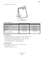
Keep the ESD-sensitive part in its original shipping container (a special “ESD bag”) until you are ready to
install the part into the machine.
•
Make the least-possible movements with your body to prevent an increase of static electricity from clothing
8fibers, carpets, and furniture.
•
Put the ESD wrist strap on your wrist. Connect the wrist band to the system ground point. This discharges
any static electricity in your body to the machine.
•
Hold the ESD-sensitive part by its edge connector shroud (cover); do not touch its pins. If you are removing
a pluggable module, use the correct tool.
•
Do not place the ESD-sensitive part on the machine cover or on a metal table; if you need to put down the
ESD-sensitive part for any reason, first put it into its special bag.
•
Machine covers and metal tables are electrical grounds. They increase the risk of damage, because they
make a discharge path from your body through the ESD-sensitive part. (Large metal objects can be discharge
paths without being grounded.)
•
Prevent ESD-sensitive parts from being accidentally touched by other personnel. Install machine covers
when you are not working on the machine, and do not put unprotected ESD-sensitive parts on a table.
•
If possible, keep all ESD-sensitive parts in a grounded metal cabinet (case).
•
Be extra careful in working with ESD-sensitive parts when cold-weather heating is used, because low
humidity increases static electricity.
Model information used in the parts catalog
When replacing parts, always check the serial number label on the rear of the machine for the machine
type/model number. Match the machine type/model number with the machine type model that is referenced
in the parts catalog for the part being replaced. There is also a label inside the front door of the machine.
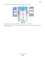
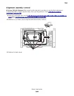
Polygon printhead mechanical registration adjustment
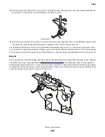
Do the printhead mechanically registration adjustment whenever you remove or replace the printhead or loosen
the mounting screws.
Install the new printhead with the mounting screws centered in the slots in the printhead frame assembly. Leave
the screws loose enough to allow the printhead to move from side to side within the slots. It is necessary to
perform a mechanical registration adjustment before locking down the three printhead mounting screws.
Note:
In the case of paper feed skew, go to
“Alignment assembly adjustment” on page 305
.
1
Turn the printer off.
2
Press and hold 3 and 6 to enter the diagnostic mode.
3
Turn the printer on, and release the buttons when
Performing Self Test
displays.
4
Select
Registration
from the menu.
7462
Repair information
304
Summary of Contents for 7462 series
Page 26: ...7462 26 ...
Page 30: ...7462 30 ...
Page 38: ... Analog or digital multimeter Flashlight optional 7462 General information 38 ...
Page 288: ...7462 288 ...
Page 346: ...5 Remove the pins D on both sides securing the links C A B D 7462 Repair information 346 ...
Page 348: ...9 Lift the operator panel door assembly out of the machine 7462 Repair information 348 ...
Page 416: ...A 3 Remove the anti tip latch assembly 7462 Repair information 416 ...
Page 419: ...A 3 Remove the HCIT tray cover front 7462 Repair information 419 ...
Page 564: ...7462 564 ...
Page 566: ...7462 566 ...
Page 571: ...7462 571 ...
Page 576: ...7462 Parts catalog 576 ...
Page 581: ...Assembly 4 Media path and ducts 1 2 3 4 5 6 7 8 9 10 11 14 13 12 3 7462 Parts catalog 581 ...
Page 591: ...Assembly 9 Fuser and LVPS card assemblies 1 4 2 3 5 6 7 8 9 10 7462 Parts catalog 591 ...
Page 595: ...Assembly 11 ADF unit assembly 1 7462 Parts catalog 595 ...
Page 597: ...Assembly 12 ADF covers 1 2 3 4 5 6 7 8 9 10 11 12 7462 Parts catalog 597 ...
Page 599: ...Assembly 13 ADF feed and drive 7462 Parts catalog 599 ...
Page 601: ...7462 Parts catalog 601 ...
Page 602: ...Assembly 14 ADF electronics 7462 Parts catalog 602 ...
Page 604: ...7462 Parts catalog 604 ...
Page 607: ...7462 Parts catalog 607 ...
Page 610: ...7462 Parts catalog 610 ...
Page 613: ...7462 Parts catalog 613 ...
Page 616: ...7462 Parts catalog 616 ...
Page 617: ...Assembly 19 MFP stapler assembly 1 1 7462 Parts catalog 617 ...
Page 621: ...Assembly 21 MFP stapler assembly 3 4 5 1 2 3 6 6 7 8 9 10 11 7462 Parts catalog 621 ...
Page 623: ...Assembly 22 MFP stapler assembly 4 1 2 7462 Parts catalog 623 ...
Page 625: ...Assembly 23 MFP offset stacker assembly 1 1 7462 Parts catalog 625 ...
Page 629: ...Assembly 25 MFP offset stacker 3 4 5 1 2 3 6 6 7 8 9 10 11 7462 Parts catalog 629 ...
Page 631: ...Assembly 26 MFP 4 bin mailbox assembly 1 1 7462 Parts catalog 631 ...
Page 633: ...Assembly 27 MFP 4 bin mailbox assembly 2 3 2 4 5 11 8 9 10 7 1 6 7462 Parts catalog 633 ...
Page 637: ...Assembly 29 Envelope feeder 1 7462 Parts catalog 637 ...
Page 642: ...7462 Parts catalog 642 ...
Page 644: ...7462 644 ...
Page 684: ...7462 684 ...
Page 698: ...7462 Index 698 ...