


5
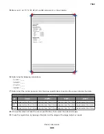
Select
Quick Test Page
. The test page should only be printed on letter or A4 paper from Tray 1. The Quick
Test Page consists of alignment diamonds, horizontal lines that can be used for mechanical registration
adjustment. An example of the printhead alignment printout is shown below:
Loader
Kernel
Base
Network
Netwrk Drvr
Engine
Panel
Font
LF.LBH.P055-0
FFN.APS.F191a-0
LF.LBH.P055-0
NF.APS.N179-0
LF.LBH.P055-0
AF.LB.E037-0
9.9
8.31M02-U5.0
Lexmark Hd
Quick Test
Device Information
Printer Revision Levels
Printer Margin Settings
Page Cou nt
Installed Memory
Processor Speed
31
192 MB
467MHz
Serial Number
0116413
TDS Calibration
00 14 FF 00 00 00 00
Engine ID
40
System Card ID
0004007E24A2
Top Margin
= 5
Bottom Margin
= 0
Left Margin
Right Margin
Dup Top Margin
Dup Left Margin
Paper Source
Formatted Size
= -3
= 0
= 0
= 0
= Tray 1
= Letter
Darkest bar indicates
ADJUSTMENT AMOUNT
for bidirectional alignment
- 12
- 10
- 8
- 6
- 4
- 2
0
+ 2
+ 4
+ 6
+ 8
+ 10
+ 12
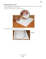
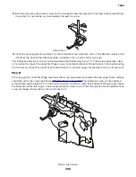
Check the Quick Test Page for any sign of misalignment by checking the diamonds at the top left and top
right of the test page for equal distance from the top of the page. If necessary, rotate the printhead to the
left or right and tighten down the mounting screws and check for proper alignment again by running another
Quick Test Page. This procedure may take two or three attempts before you get satisfactory results.
6
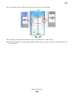
When you have the correct adjustment, ensure that the printhead mounting screws are properly tightened.
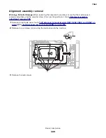
Alignment assembly adjustment
Do the alignment assembly adjustment whenever you replace the alignment assembly. Always print a copy of
the Quick Test Page before making any adjustments to the alignment assembly reference adjustment screw.
When replacing the alignment assembly, it is necessary to back the reference adjustment screw out far enough
to remove the old assembly and install the new one.
•
If you are replacing the alignment assembly, go to step A.
•
If you are only adjusting the reference adjustment screw, go to step B.
Step A
Print a copy of the Quick Test Page and check the margin adjustments printed on the test page. These settings
should be within the range specified in
Do the reference adjustment if you are sure the margins are set correctly.
1
Loosen the locknut on the inside rear of the alignment assembly.
2
Remove the two screws holding the alignment assembly to the left side frame.
7462
Repair information
305
Summary of Contents for 7462 series
Page 26: ...7462 26 ...
Page 30: ...7462 30 ...
Page 38: ... Analog or digital multimeter Flashlight optional 7462 General information 38 ...
Page 288: ...7462 288 ...
Page 346: ...5 Remove the pins D on both sides securing the links C A B D 7462 Repair information 346 ...
Page 348: ...9 Lift the operator panel door assembly out of the machine 7462 Repair information 348 ...
Page 416: ...A 3 Remove the anti tip latch assembly 7462 Repair information 416 ...
Page 419: ...A 3 Remove the HCIT tray cover front 7462 Repair information 419 ...
Page 564: ...7462 564 ...
Page 566: ...7462 566 ...
Page 571: ...7462 571 ...
Page 576: ...7462 Parts catalog 576 ...
Page 581: ...Assembly 4 Media path and ducts 1 2 3 4 5 6 7 8 9 10 11 14 13 12 3 7462 Parts catalog 581 ...
Page 591: ...Assembly 9 Fuser and LVPS card assemblies 1 4 2 3 5 6 7 8 9 10 7462 Parts catalog 591 ...
Page 595: ...Assembly 11 ADF unit assembly 1 7462 Parts catalog 595 ...
Page 597: ...Assembly 12 ADF covers 1 2 3 4 5 6 7 8 9 10 11 12 7462 Parts catalog 597 ...
Page 599: ...Assembly 13 ADF feed and drive 7462 Parts catalog 599 ...
Page 601: ...7462 Parts catalog 601 ...
Page 602: ...Assembly 14 ADF electronics 7462 Parts catalog 602 ...
Page 604: ...7462 Parts catalog 604 ...
Page 607: ...7462 Parts catalog 607 ...
Page 610: ...7462 Parts catalog 610 ...
Page 613: ...7462 Parts catalog 613 ...
Page 616: ...7462 Parts catalog 616 ...
Page 617: ...Assembly 19 MFP stapler assembly 1 1 7462 Parts catalog 617 ...
Page 621: ...Assembly 21 MFP stapler assembly 3 4 5 1 2 3 6 6 7 8 9 10 11 7462 Parts catalog 621 ...
Page 623: ...Assembly 22 MFP stapler assembly 4 1 2 7462 Parts catalog 623 ...
Page 625: ...Assembly 23 MFP offset stacker assembly 1 1 7462 Parts catalog 625 ...
Page 629: ...Assembly 25 MFP offset stacker 3 4 5 1 2 3 6 6 7 8 9 10 11 7462 Parts catalog 629 ...
Page 631: ...Assembly 26 MFP 4 bin mailbox assembly 1 1 7462 Parts catalog 631 ...
Page 633: ...Assembly 27 MFP 4 bin mailbox assembly 2 3 2 4 5 11 8 9 10 7 1 6 7462 Parts catalog 633 ...
Page 637: ...Assembly 29 Envelope feeder 1 7462 Parts catalog 637 ...
Page 642: ...7462 Parts catalog 642 ...
Page 644: ...7462 644 ...
Page 684: ...7462 684 ...
Page 698: ...7462 Index 698 ...