


Page 7
SCENE 1 SCENE 2 SCENE 3 SCENE 4
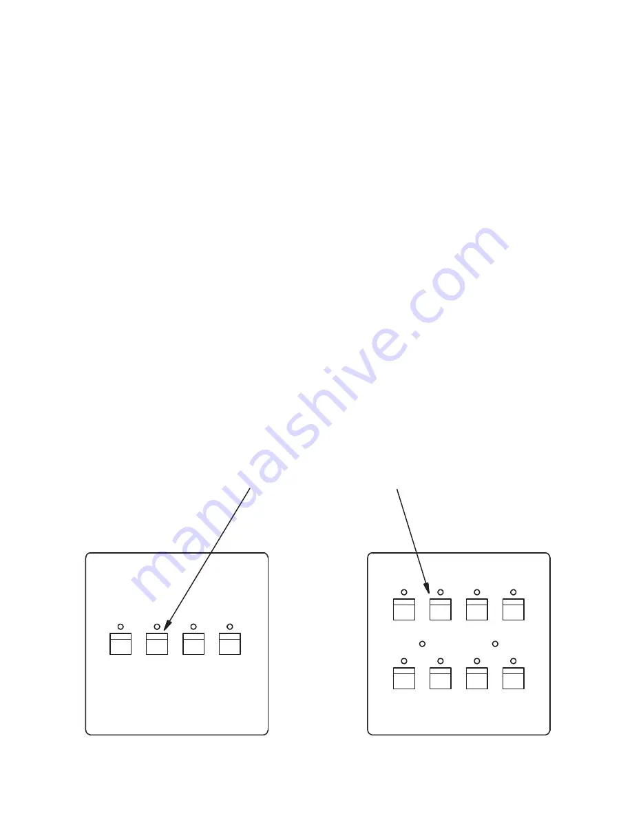
DIMMER LEVEL MODE
SCENE 1 SCENE 2 SCENE 3 SCENE 4
SCENE 5 SCENE 6 SCENE 7 SCENE 8
LUMA-NET
LUMA-NET
404 CP
408 CP
DOWN UP INCREASE DECREASE
DOWN UP INCREASE DECREASE
PWR
BUSY
Assigning dimmer channels to each scene.
Each of the scenes of the 404CP and 408CP must be programmed with the desired levels for
each dimmer assigned to the scene.
In order to easily identify dimmer channels while programming, the system should have all
installed lamps or loads operational. If this is not possible, the panel to be programmed should
be temporarily connected nearby to the dimmer units so that the control LEDs of the dimmers
may be observed to verify channel selection.
To program each scene:
1.
Make sure that the 404CP or 408CP is in the program select mode as discussed. The
BUSY LED should be flashing.
2.
Press the SCENE 1 button to select “dimmer level mode” and the BUSY LED will stop
flashing.
3.
Press button representing desired scene to be programmed. At this point, all currently
assigned dimmers will come on to the currently programmed levels (normally at zero
brightness). The current dimmer selector will be set to the first previously assigned dimmer.
4.
Use the buttons marked as UP and DOWN in diagram to increment or decrement the
dimmer channel selector through the assigned dimmers. Tap the buttons the required
number of times to reach the dimmer channel to be programmed.
5.
Use the INCREASE and DECREASE buttons to change the dimmer brightness. The lamps
connected to this dimmer channel will come on full when the INCREASE button is pressed
and held down. A tap of the INCREASE or DECREASE button will cause a fine change in
brightness, a push and hold motion will cause a rapid change. Observe lamps or dimmer
LEDs to verify correct channel has been selected.
6.
Next, exit this programming mode; press both the UP and DOWN buttons at the same time.
The BUSY LED will start flashing again when both buttons are released.
7.
A new scene can be programmed at any time by following the above procedure.
WEB
VERSION


