


Description of Hardware
1-3
1
Description of Hardware
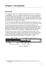
10/100/1000BASE-T Ports
The switch contains 24 RJ-45 ports that operate at 10 Mbps or 100 Mbps, half or full
duplex, or at 1000 Mbps, full duplex. Because all ports on the switch support
automatic MDI/MDI-X operation, you can use straight-through cables for all network
connections to PCs or servers, or to other switches or hubs. (See 1000BASE-T Pin
Assignments on page B-3.)
Each of these ports support auto-negotiation, so the optimum transmission mode
(half or full duplex), and data rate (10, 100, or 1000 Mbps) can be selected
automatically. If a device connected to one of these ports does not support
auto-negotiation, the communication mode of that port can be configured manually.
SFP Slots
The Small Form Factor Pluggable (SFP) transceiver slots are shared with four of the
RJ-45 ports (ports 21~24). In its default configuration, if an SFP transceiver
(purchased separately) is installed in a slot and has a valid link on its port, the
associated RJ-45 port is disabled and cannot be used. The switch can also be
configured to force the use of an RJ-45 port or SFP slot, as required.
10 Gigabit Ethernet Module Slots
The switch includes two slots on the rear panel for hot-swappable single-port
10GBASE modules with XFP transceivers. Refer to Optional Media Extender
Modules on page 1-6 for more information on this module and the supported 10G
transceivers.
Stacking Ports
Each unit includes two stacking ports that provide a 48 Gbps high-speed serial stack
backplane connection. Up to eight 24-port switches can be connected together
using optional stacking cables. Note that the 24-port switch can be mixed in the
same stack. The Stack Master button enables one switch in the stack to be selected
as the Master unit for managing the entire stack.
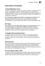
Port and System Status LEDs
The switch includes a display panel for key system and port indications that simplify
installation and network troubleshooting. The LEDs, which are located on the front
panel for easy viewing, are shown below and described in the following tables.
Summary of Contents for GTL-2690
Page 2: ......
Page 4: ......
Page 18: ...xiv Figures ...
Page 26: ...Introduction 1 8 1 ...
Page 34: ...2 8 Network Planning 2 ...
Page 44: ...3 10 Installing the Switch 3 ...
Page 56: ...A 4 Troubleshooting A ...
Page 62: ...B 6 Cables B ...
Page 73: ...Index Index 3 V VLANs routing 2 6 tagging 2 5 W web based management 1 2 ...
Page 74: ...Index Index 4 ...
Page 75: ......


