Calculated Iout do not exceeds the output working range (3.8 - 21 mA).
b) D = „20.5”
According to formula from page 34:
I
out
= (20.5-10.0) / (20.0-10.0) × 16 mA + 4 mA = 1.05 ·16 + 4 = 20.08 mA
Calculated Iout do not exceeds the output working range (3.8 - 21 mA).
c) D = „30.0”
According to formula from page 34:
I
out
= (30.0-10.0) / (20.0-10.0) × 16 mA + 4 mA = 2 ·16 + 4 = 36 mA.
Calculated Iout exceeds the output working range (3 - 21 mA), so current output will generate
current equal to the upper border of range defined by parameter
“Lo r”
i
“Hi r”
(it means 21 mA).
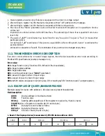
Transmission parameters : 1 start bit, 8 data bits, 1 or 2 stop bit (2 bits are send, 1 and 2 bits are accepted
when receive), no parity control
Baud rate : selectable from: 1200 to 115200 bits/second
Transmission protocol : MODBUS RTU compatible
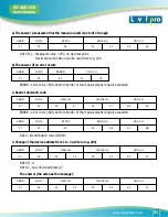
The device parameters and display value are available via RS-485 interface, as HOLDINGtype registers
(numeric values are given in U2 code) of Modbus RTU protocol. The registers (or groups of the registers) can
be read by 03h function, and wrote by 06h (single registers) or 10h (group of the registers) accordingly to
Modbus RTU specification. Maximum group size for 03h and 10h functions can not exceeds 16 registers (for
single frame).
11. THE MODBUS PRO TOCOL HANDLING
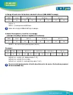
The device interprets the broadcast messages, but then do not sends the answers.
44
www. levelprosales.com
ITC 450/470
User manual
Summary of Contents for ITC 450
Page 14: ...www levelprosales com 12 www levelprosales com ITC 450 470 User manual...
Page 17: ...www levelprosales com 15 www levelprosales com ITC 450 470 User manual...
Page 38: ...36 www levelprosales com ITC 450 470 User manual 7 4 MENU STRUCTURE...
Page 39: ...37 www levelprosales com ITC 450 470 User manual...


