background image


(BRANCH CIRCUIT)


WIRING


To connect motor for proper voltage and rotation, refer to connection diagram on nameplate or inside terminal/conduit box. If power factor 

correction capacitors are used for individual motor power factor correction, do not exceed maximum recommended value. 

All aspects of the installation must conform to the requirements of the NEC, including Article 430 (Motor Circuits and Controllers), and all 

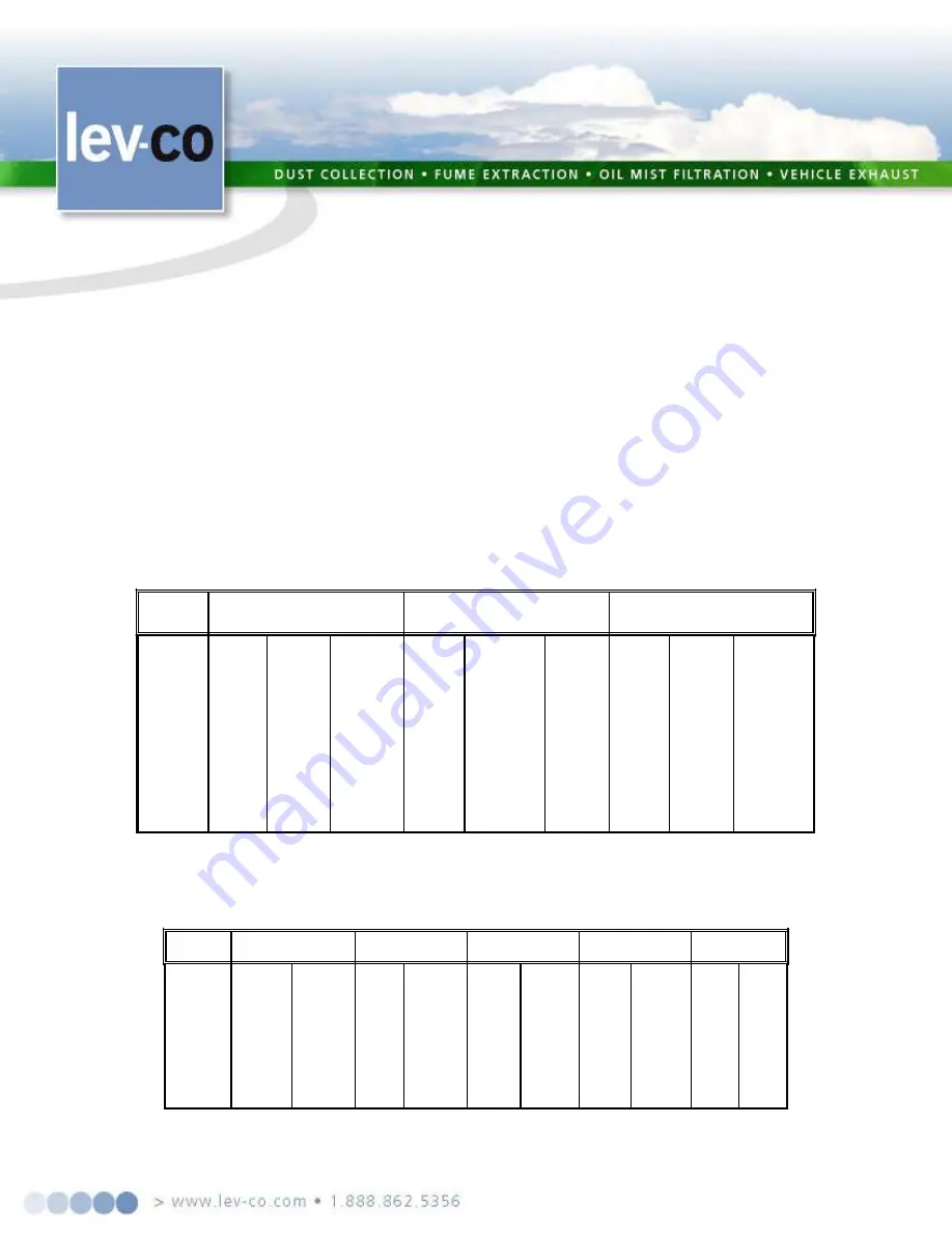
local codes. Wherever possible, each motor should be powered from a separate circuit of adequate capacity to keep voltage drop to a minimum during 
starting and running.  Increase wire size where motor is located a distance from the power source. Wire size must be adequate to minimize voltage drop 
during starting and running. Refer to Tables A and B for suggested wire sizes. Distances shown are one-way between source and load.  Portable cords, if 
used, should be as short as possible to minimize voltage drop. Long or inadequately sized cords, especially on hard starting loads, can cause motor 
failure. Insulate and protect motor lead connections to prevent cut-through from sharp edges and vibration. Tape wire nuts to prevent loosening. All 
electrical connections in system must be secure to prevent voltage drop and localized heating. 

Determine direction of rotation before connecting driven equipment to prevent damage.  Remove shaft key if motor is to be operated at no- 

load. On three phase motors, interchange any two line leads (not motor leads) to reverse rotation. On air compressors, rotation of flywheel should direct 
air towards the cylinders.  Look for rotational arrow on flywheel. 

All motors must be securely and adequately grounded by wiring with a grounded, metal-clad raceway system, using a separate ground bond 

wire connected to bare metal on the motor frame, or other suitable means. Refer to NEC Article 250 (Grounding) for additional information. 

Explosion-proof motors incorporating overtempature thermostats should be controlled with a magnetic starter. The thermostat circuit must be 

wired in series with the holding coil circuit, as shown on tag or nameplate on motor, to remove power from the starter coil if motor overheats. 

TABLE A - MINIMUM WIRE SIZES FOR THREE-PHASE MOTORS


[*]Type S, SO, SJ, SJO, etc. flexible cable wire sizes.  See NEC Article 400 for ampacity

.


Note: 

Above wire sizes based on approximate 5% voltage drop during starting; copper conductors; and 75°C type TH, THW, RH, RHW, etc. insulation. For aluminum 

wire, increase two wire size steps minimum. See NEC Article 310 for ampacities of aluminum conductors and 60°C type RUW, T, etc. insulation

.


TABLE B - MINIMUM WIRE SIZES FOR SINGLE-PHASE MOTORS


[*] Type S, SO, SJ, SJO, etc. flexible cable wire sizes.  See NEC Article 400 for ampacity.


Note:  

Above wire sizes based on approximate 5% voltage drop during starting; copper conductors;and 75°C type TH, THW, RH, RHW, etc. insulation.  For aluminum wire, 

increase two wire size steps minimum.  See NEC Article 310 for ampacities of aluminum conductors and 60°C type RUW, T, etc. insulation. 

Page: 

14/15 .


MOT0R 

HP


25 

FT


115V 

230V


50 

FT


115V 

230V


100 

FT


115V 

230V


150 

FT


115V 

230V


200 

FT


115V 

230V


1/8 
1/6 
1/4 
1/3 
1/2 
3/4 

1½ 


14(16)* 

14 
14 
14 
14 
12 
10 
10 


14(18)* 
14(18)* 
14(18)* 
14(18)* 
14(18)* 
14(18)* 
14(16)* 
14(16)* 

14 
10 

14 
12 
12 
10 
10 


14(18)* 
14(18)* 
14(18)* 
14(16)* 
14(16)* 

14 
14 
12 
12 
10 

10 
10 


14(16)* 
14(16)* 

14 
14 
14 
12 
10 
10 


10 


1/0 

14(16)* 

14 
12 
12 
12 
10 


1/0 
2/0 

14 
12 
12 
10 
10 


MOTOR 

HP


25 FT 

TO 

50 FT


200V 

230V 

460V


100 FEET


200V 

230V 

460V


150 FT 

TO 

200 FT


200V 

230V 

460V


1/8 

1/6 

1/4 

1/3 

1/2 

3/4 

1½ 

14(18)* 

14(18)* 

14(18)* 

14(18)* 

14(16)* 

14 

14 

12 

12 

10 

14(18)* 

14(18)* 

14(18)* 

14(18)* 

14(18)* 

14(16)* 

14(16)* 

14 

12 

12 

14(18)* 

14(18)* 

14(18)* 

14(18)* 

14(18)* 

14(18)* 

14(18)* 

14(18)* 

14(18)* 

14(18)* 

14(18)* 

14(18)* 

14(16)* 

14(16)* 

14 

12 

10 

10 

14(18)* 

14(18)* 

14(18)* 

14(16)* 

14 

14 

12 

10 

10 

14(18)* 

14(18)* 

14(18)* 

14(18)* 

14(18)* 

14(18)* 

14(18)* 

14(16)* 

14(16)* 

14 

14(16)* 

14(16)* 

14 

12 

10 

14(18)* 

14(16)* 

14 

14 

12 

10 

10 

14(18)* 

14(18)* 

14(18)* 

14(18)* 

14(18)* 

14(16)* 

14 

14 

12 

12 

MOTOR WIRING GUIDE


Summary of Contents for Multi-flex

Page 1: ...RECTED ALL THE POTENTIAL HAZARDS OF DUST AND MIST CONTROL SYSTEMS AND EQUIPMENT ARE IMPOSSIBLE TO LIST THEREFORE OBTAIN THE SERVICES OF A PROFESSIONAL INSTALLER A FIRE PROTECTION EXPERT SHOULD BE OBTAINED IN THE EVENT THE PRODUCT IS INTENDED FOR USES WHICH PRESENT A POTENTIAL RISK OF FIRE OR FIRE PROPAGATION REFER TO APPROPRIATE AUTHORITIES AND DISCUSS YOUR INTENDED USE WITH A LEV CO REPRESENTANT ...

Page 2: ...LTERS TO MAINTAIN WARRANTY TO ORDER SPARE PARTS CONTACT US 1050 BROCK ROAD Unit 22 24 Pickering ON CANADA L1W 3X4 Phone 905 831 7001 or 888 862 5356 Fax 905 831 7443 or 866 840 9923 E mail sales lev co com Website http www lev co com Page 2 15 ...

Page 3: ...READ INSTRUCTIONS CAREFULLY BEFORE ATTEMPTING TO INSTALL OPERATE OR SERVICE YOUR MODEL MINI VAC UNIT RETAIN THESE INSTRUCTIONS FOR FUTURE REFERENCE Page 3 15 ...

Page 4: ...e hoods and dust collector should be provided so that a fire protection specialist can install extinguishing equipment You may also want to contact your insurance underwriter 4 Always disconnect unit from power source before inspecting or servicing LEV CO SETS THE STANDARD The Lev co MULTI FLEX collects dust welding smoke mist and other atmospheric pollutants in industrial plants shops schools and...

Page 5: ...tant paint Includes side access doors dust pan door 5 casters self supporting 6 75 dia by 10 long extractor arm and ULTRA SEAL filter sealing system to prevent by pass NOISE LEVEL ELECTRICAL Standard Motor STD 78 dBA 5 68 dBA 5 with optional silencer 1 5 HP 115 208 230 1 60 17 0 8 5 A Opt 1 5 HP 208 230 460 3 60 4 9 4 6 2 3 A Opt 3 HP HP 208 230 460 575 3 60 8 0 4 0 A STD 2 HP 208 230 460 575 3 60...

Page 6: ...or blower compartments for any packing materials and remove PREPARATION AND INSTALLATION After initial inspection for shipping damage open the cabinet and motor access door Remove all packing materials and filters to avoid damage and to facilitate the installation The installation should conform to all local ordinances associated with building and electrical codes required for the unit Authorities...

Page 7: ...ld be performed with the unit running all filters in place and cabinet doors closed Measured motor current readings should be equal to or below motor nameplate rating These specifications can be found on the motor name plate or in the specifications section of this manual The single phase 115V AC motors supplied in the MULTI FLEX have thermal overload protection Motor rotation may be changed if re...

Page 8: ...s will produce this result e g reverse L1 and L2 or L2 and L3 Figure 5 shows the electrical hook ups on the three phase motor Figure 5 CAUTION OTHER OPTIONS ELECTRICAL The standard Light Kit will require an additional 4 0 A at 115V AC minimum be sure to add this into the power requirements when allocating circuits for the MULTI FLEX unit The standard light will come on only when the unit is operat...

Page 9: ...ion is noticed or on models so equipped when the optional pressure gauge indicates a restriction The optional pressure gauge is calibrated as follows With clean filters turn unit on and mark the pressure reading on the gauge see diagram included with gauge for hook up Make a second mark at 2 0 higher than initial reading i e if initial reading is 1 0 the second mark should be at 3 0 Whether using ...

Page 10: ...1 Turn unit off and unplug from electrical circuit 2 Remove filter access panel 3 Clean or replace pre filter per above instructions 4 Release filter retaining clamps located on filter holding frame see Figure 6 5 Slide filters out of the holding frame 6 To replace reverse the procedure above HEPA FILTER on models so equipped cannot be cleaned See your distributor for replacement OTHER SERVICE Mos...

Page 11: ... vibration noise and short bearing life and clean as necessary An occasional drop of oil on the caster wheel bearing will keep them moving freely Replacement parts are available from your Lev co distributor The following section lists replacement parts for the MULTI FLEX unit REPLACEMENT PARTS Page 11 15 ...

Page 12: ...ors 3 Replace transformer With voltmeter check input volts and 12 volt output 4 Check circuit breaker 4 No input voltage 2 Motor won t operate 1 Motor overload 1 Too much airflow Be sure arm hose or ducts and doors are installed before running 2 Replace motor Check amps to ensure proper operation 3 Check overload reset Check magnet coil for failure 4 Check circuit breaker 2 Failed motor 3 Relay or...

Page 13: ...LA FROM NAMEPLATE MOTOR VOLTAGE FROM NAMEPLTE ALWAYS USE LEV CO REPLACEMENT PARTS AND FILTERS TO MAINTAIN WARRANTY TO ORDER SPARE PARTS CONTACT LEV CO 1050 BROCK ROAD Unit 22 24 Pickering ON CANADA L1W 3X4 Phone 905 831 7001 or 888 862 5356 FAX 905 831 7443 or 866 840 9923 E MAIL sales lev co com INTERNET http www lev co com Page 13 15 ...

Page 14: ...orporating overtempature thermostats should be controlled with a magnetic starter The thermostat circuit must be wired in series with the holding coil circuit as shown on tag or nameplate on motor to remove power from the starter coil if motor overheats TABLE A MINIMUM WIRE SIZES FOR THREE PHASE MOTORS Type S SO SJ SJO etc flexible cable wire sizes See NEC Article 400 for ampacity Note Above wire ...

Page 15: ...common answers to electrical problems The information is not all inclusive and does not necessarily apply in all cases When unusual operating conditions repetitive failures or other problems occur consult an electric motor service firm for assistance Page 15 15 ...

Reviews: