PicSight GigE Getting Started Guide, version 1.96.169.1
7
2.2.2.
RS-232c, Power
Hirose 6-pin connector male, HR10A-7R-6PB-73
Pin
Signal
1
TXD Output
2
RXD Input
3
Ground
4
Reserved
5
Ground
6
10-15V DC Power Input (+)
2.3.
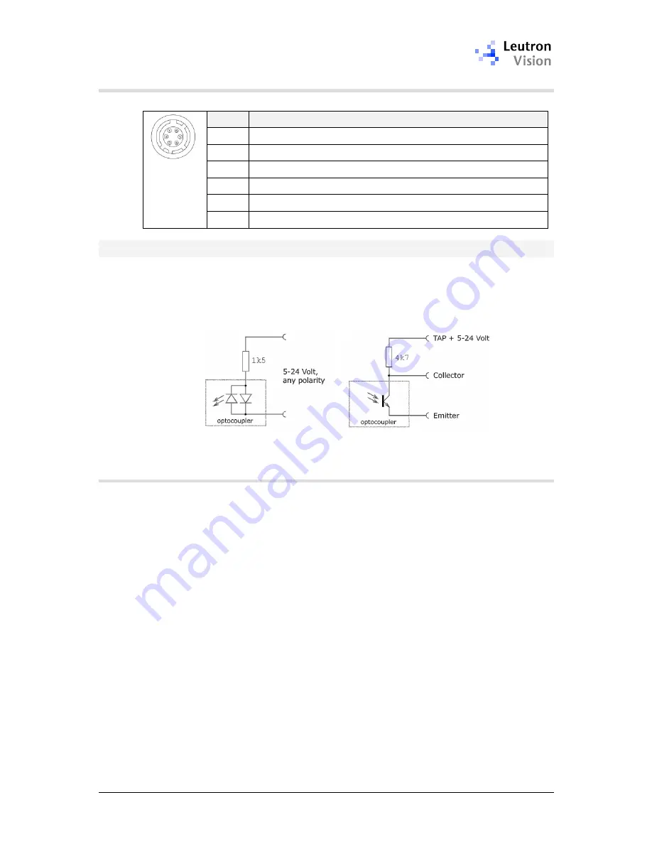
The Optocoupler Interface
For use in industrial environment, PicSight
®
boards provide I/O signals isolated
by use of optocouplers with variable 5V to 24V interface. To take full profit of
this signal isolation, you have to connect the optocoupler to an external power
supply. In the following figure is the common way, how to connect the
optocoupler to an external power source of 5-24 Volt:
2.3.1.
The Trigger Inputs
For triggering either the
optocoupler input
or the
TTL input
can be used. There is
a difference in the way the trigger is handled:
The
TTL trigger
line goes directly to the camera module and therefore the
pulse width on the TTL input defines the exposure time (if the module is set to
the
pulse width triggered
mode). Note that the polarity of the TTL trigger cannot
be configured by software; the trigger start is always the positive edge of the
pulse on the Hirose TTL input. In LV-SDS the TTL trigger input on the Hirose
connector has index
5
(the internal TTL inputs 0-4 are not connected to any
connector).
The
Opto input
is not directly connected to the camera module. Therefore the
pulse on the optocoupler generates internally an interrupt and the interrupt
handler creates a TTL trigger with the length corresponding to the shutter time,
which was preset by software. The interrupt is only raised upon a specific edge
and thus the pulse width on the opto-input does not have any influence. So the
trigger on the opto-input behaves like the
edge pre-select
trigger mode,
regardless of the trigger mode actually set. The expected polarity on opto inputs
can be configured by software on the host side.


