10
INSTALLATION AND MAINTENANCE
CPLS drip-proof 3-phase induction motors
4240 en - 2014.09 / b
LEROY-SOMER
The use of incremental encoders in industrial environments
comprising high-current installations, or electronic drive
control systems, requires industry-standard, well-known basic
rules to be followed. Equipment must be connected by qualified
personnel.
Basic rules
Use shielded cables. For connections longer than 10 metres,
use cables with several shielded twisted pairs, reinforced with
external shielding. We recommend the use of conductors with
a minimum standard cross-section of 0.14 mm² (recommended
cable type: LIYCY 0.14 mm²).
Keep the encoder connection cables as far away as possible
from the power cables and avoid parallel routing.
Distribute and connect the 0 V and the shielding in a “star”
arrangement.
Earth the shielding using cables with a minimum cross-section
of 4 mm².
Never connect the shielding to earth at both ends. Ideally,
a shielded cable should be earthed at the “User” side for the
encoder signals (cabinet, PLC, meter).
Check the continuity of the shielding when using connectors or
connection boxes.
Precautions during connection
Switch off the power supply before performing any connection
operation (connection or disconnection, with or without
connectors) at the encoder or cabinet end.
For reasons of synchronisation, power up and power down the
encoders and any associated electronic devices
simultaneously.
On the first power-up, check that the “” terminal is
supplying the required voltage before connection.
For the supply, use stabilised power supplies.
Power supplies via transformers providing 5 V (or 24 V) rms,
followed by rectifiers and smoothing capacitors, MUST NOT
BE USED, as in reality the resulting D.C. voltages obtained are:
For 5 V: 5 × √2 = 7.07 V
For 24 V: 24 × √2 = 33.94 V
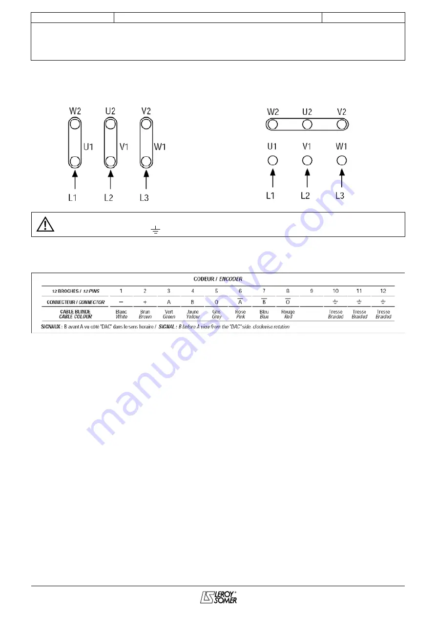
3-phase forced ventilation wiring
D
connection: 220 - 240 V
Y connection: 380 - 415 V
The forced ventilation motor must be earthed. An earth terminal is inside the ventilation motor terminal box.
It is indicated by the symbol:
Encoder wiring
Summary of Contents for CPLS 112
Page 27: ......


