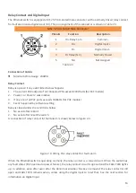
Leonton PG5-1600-M12XB-10GSFP-24-T67 Hardware User Manual Download Page 16


12 

Grounding Note


Grounding and wire routing help limit the effects of noise due to electromagnetic interference (EMI). Run 


the ground connection from the ground screw to the grounding surface prior to connecting devices. The   
grounding screw symbol is shown blow in Figure 2.5.


Figure 2.5: Grounding screw symbol 


Caution: 

Using a shielded cable achieves better electromagnetic compatibility.


Attention: 

L'utilisation d'un câble blindé permet une meilleure compatibilité 

électromagnétique.


Bypass Function 

This Ethernet switch supports bypass function by two Ethernet ports (P8 and P16). When one of the Ethernet 
switches loses power, Ethernet ports (P8 and P16) will bypass the power lost Ethernet switch to prevent the 
network from disconnecting. 

Take Figure 2.6 for example, if Switch B has power failure, the bypass function will be activated automatically, 
and it will bypass Switch B and bridge P8 to P16 of Switch B, so that the data transmission path (from Switch 
A to C) can remain connected and unaffected. 


Figure 2.6: Example of bypass function 

Reset to Default 

Please perform the below steps to reset the switch to factory default setting. 

Step 1.


Reverse the Tx & Rx of the Console Cable and plug it into the console port. 

Step 2.


Restart the power. 

Step 3.


The switch will start rebooting with the port LEDs flashing. 

Step 4.


When the Status LED turns into Green, the process is completed. 

Step 5.


Remove the reversed console cable. 


Summary of Contents for PG5-1600-M12XB-10GSFP-24-T67

Page 1: ...PG5 1802 M12XB 10GSFP 24 67 PG5 1600 M12XB 10GSFP 24 T67...

Page 2: ...t not limited to the implied warranties of merchantability and fitness for a particular purpose Leonton Technologies Co Ltd may make improvements and or changes to the product and or specifications of...

Page 3: ...tions FCC Ces limites sont con ues pour fournir une protection raisonnable contre toutes interf rences nuisibles dans un milieu r sidentiel Cet quipement g n re utilise et peut mettre de l nergie de f...

Page 4: ...Front Panel 4 Bottom View 4 LED Indicators 5 Ethernet Ports 6 Fiber Port 7 USB Port 8 Console Port 8 Power Inputs 9 Relay Contact and Digital Input 10 Grounding Note 12 Bypass Function 12 Reset to De...

Page 5: ...erature of 40 C 70 C this series is designed to meet any needs for industrial automation application and harsh environments Key Features Interface Performance Copper port support auto MDI MDI X functi...

Page 6: ...externe veuillez utiliser un dispositif de protection sur l entr e d alimentation Fourniture par courant industriel homologu UL Les sp cifications mat rielles les ports les informations de c blage et...

Page 7: ...3 HARDWARE DESCRIPTION Physical Dimensions Figure 2 1 below shows the physical dimensions of PG5 1802 M12XB 10GSFP 24 67 series W x H x D is 295mm x 160mm x 101 3mm Figure 2 1 Physical Dimensions...

Page 8: ...nsure easier plugging and safer operation The LED indicates various status by different colors and shapes of the light Besides this series supports console USB DI DO and dual DC power inputs 24 55VDC...

Page 9: ...sconfigure Off ERPS Ring Network is not active PoE Load Off The current overall PoE output power divided by power budget is 50 Blue On The current overall PoE output power divided by power budget is 5...

Page 10: ...BI_DD 6 BI_DD 7 BI_DC 8 BI_DC Table 2 2 Note and signs represent the polarity of the wires that make up each wire pair Connection of Cables Use the twisted pair cable category 5e or the above cabling...

Page 11: ...module which needs to be replaced Step 2 Put the fiber cable through the metal end lock sealing and cap Step 3 Insert the SFP transceiver into the Metal Panel Lock and tighten and seal all parts Caut...

Page 12: ...on backup restore M12 connector M12 4 Pin A Coded female Connector Pinouts Function 1 DN 2 VBUS 3 GND 4 DP Console Port It is a M12 5 Pin A Coded female connector Baud rate 115 200bps 8 N 1 M12 connec...

Page 13: ...assignment M12 5 Pin K Coded Male Connector Pinouts Function 1 V1 2 V1 3 V2 4 V2 5 GND Table 2 3 Connection of Cables Minimum Wire Gauge 18AWG Please follow the below steps to insert the power wire St...

Page 14: ...Power 1 or Power 2 was inactive 3 If any one of all PoE ports exceeds 30Watts for PoE models 4 Event happened by software setting Relay is closed under the conditions below 1 No event after reboot 2...

Page 15: ...tage the DI function will be triggered Table 2 5 is shown a detail specification of the digital input Specification Description Level 0 Low 30 8VDC Will trigger DI function active trigger states Level...

Page 16: ...es loses power Ethernet ports P8 and P16 will bypass the power lost Ethernet switch to prevent the network from disconnecting Take Figure 2 6 for example if Switch B has power failure the bypass funct...

Page 17: ...nded use the M5 screws Step 2 Based on the Figure 3 2 Physical Dimensions which is shown the positions of 4 screw holes on the left and right side of the switch to make 4 screw holes on a wall accordi...

Page 18: ...d help on how to wire power please refer to the Power Inputs section Please refer to the LED Indicators section for LED light indication Step 4 Prepare the M12 cable for Ethernet connection Step 5 Ins...

Page 19: ...st me int grant l quipement est de la responsabilit de l assembleur du syst me Caution This is an OPEN TYPE module and should be installed in a final safety enclosure characteristic Attention Il s agi...

Page 20: ...which help to identity if any problems exist Please refer to the LED Indicators section for LED light indication If the power indicator LED does not turn on when the power cord is plugged in the user...

Reviews: