


10
Relay Contact and Digital Input
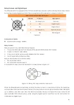
The Ethernet switch is equipped a M12 5-Pin A-Coded male connector with a normally closed relay contact
for fault alarm and a digital input (DI). The pin assignment of this connector is shown in Table 2.4.
M12 5-Pin A-Coded Male Connector
Pinouts
Function
Description
1
DI+ Relay Com
Common
2
DI+
Digital Input +
3
DI-
Digital Input -
4
DI- Relay (N.C.)
Normally Closed
5
NA
Not Assigned
Table 2.4
Connection of Cables
⚫
Minimum Wire Gauge: 24AWG
Relay Contact
Relay is opened if any event listed below happens
1.
The current PoE outputs of all connected PDs exceed 240 Watts (for PoE models)
2.
Power 1 or Power 2 was inactive
3.
If any one of all PoE ports exceeds 30Watts (for PoE models)
4.
Event happened by software setting
Relay is closed under the conditions below
1.
No event after reboot
2.
No event after reset the switch
A connection of relay contact for fault alarm is shown below in Figure 2.4.
Figure 2.4: Wiring the relay contact for fault alarm
When the Ethernet switch is operating normally, the relay contact is a closed circuit. When the switch has
any fault status (PoE overload or power failure), the relay contact circuit is opened and the FAULT LED lights
up. In addition, even after even after the abnormal situation has been removed, the relay contact is
still
open and FAULT LED remains active, unless using the digital input to reset that. See the next section for
information on Digital Input.


